PACSystems VersaMax Genius Network Interface User Manual Section 5
GFK-1535D Jan 2023
Configuration 87
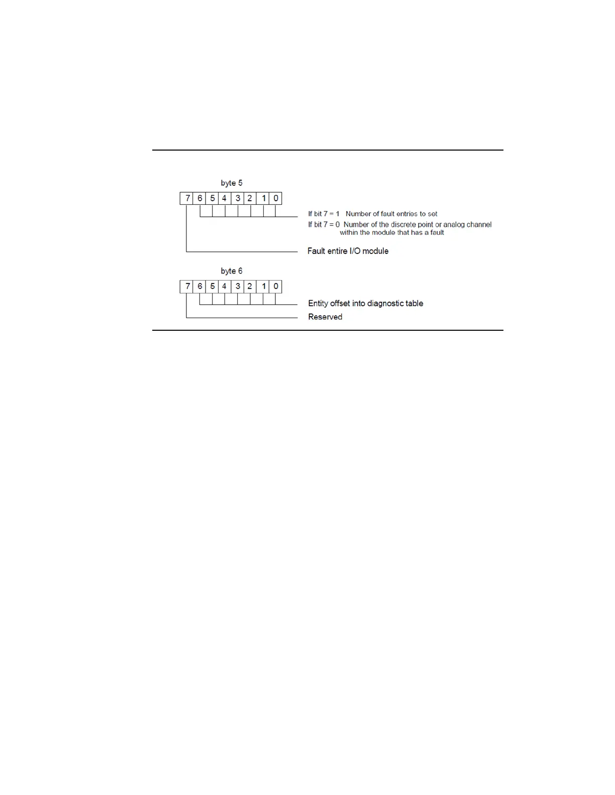
Fault Bytes 6 and 7
Fault bytes 6 and 7 (datagram bytes 5 and 6) are automatically
interpreted by PACSystems RX7i controllers, Series 90-70 PLCs, and. They
are not relevant to other types of hosts.
Figure 63: Fault Bytes 6 and 7
5.5 Configuration Data
Datagrams can be used to read and write configuration data for an I/O
Station. However, most systems will use programmer configuration or
autoconfiguration.
For a Network Interface Unit, the configuration data specifies the rack
and slot number of a specific module in the station. The length specified
must exactly match the length of the configuration data for the module
(Network Interface Unit or another module in the I/O station); partial
configuration data cannot be read or written. For programming
instructions, you should refer to the documentation set for the PLC.
Configuration files for conventional I/O modules can be read or written
one module per message. However, the configuration files of intelligent
modules may exceed the 128-byte maximum length of a Genius
message. Therefore, any Write Configuration to an intelligent module
must be contained within a Begin/End Packet Sequence.
Multiple byte fields in datagrams are transmitted in little-endian format.
In this format, the least significant byte of a word is stored in the lowest
memory location or transmitted first in time. The most significant byte
follows.