Reference Manual
00809-0100-4731, Rev FA
April 2003
1-6
APEX
™
and APEX Sentry
™
Radar Gauge
SYSTEM
ARCHITECTURE
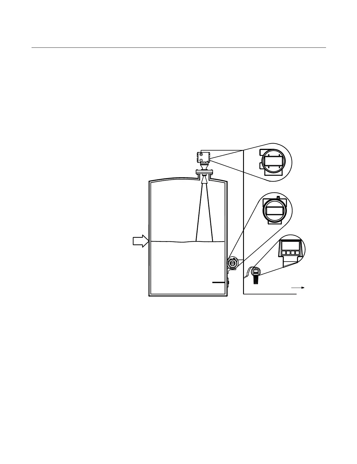
The output of the APEX and APEX Sentry Radar Gauges is a 4–20 mA
analog signal superimposed with a digital HART signal. As a result, the
primary variable (4–20 mA output) can be configured to represent either level
(APEX and APEX Sentry Radar Gauges) or calculated volume (APEX Radar
Gauge only), with up to three additional variables available through the HART
signal.
In addition to using the HART Communicator, you can view level and volume
variables using an optional Integral Display on the gauge or a Model 751 Field
Signal Indicator as a remote display (see Figure 1-2).
Figure 1-2. APEX System
Architecture and Display
Options
Level: 5.10 m
Level: 5.10 m
Level: 5.10 m
Optional
Integral Display
Model 751 Field
Signal Indicator
HART
Communicator
Level=
5.10 m
Control System
4
–
2
0
mA
/
H
A
R
T
S
i
g
n
a
l
LEVEL-0006B
 Loading...


