Reference Manual
00809-0100-4731, Rev FA
April 2003
APEX
™
and APEX Sentry
™
Radar Gauge
2-20
MECHANICAL
INSTALLATION
Mounting
Considerations
Flange Sizes
The radar gauge mounts on the top of a vessel using a 2-, 3-, 4-, or 6-inch
ASME B 16.5 (ANSI) Class (DN 50, DN 80, DN 100, or DN 150) flange.
(Flange size is specified at the time of order.)
Access Clearances
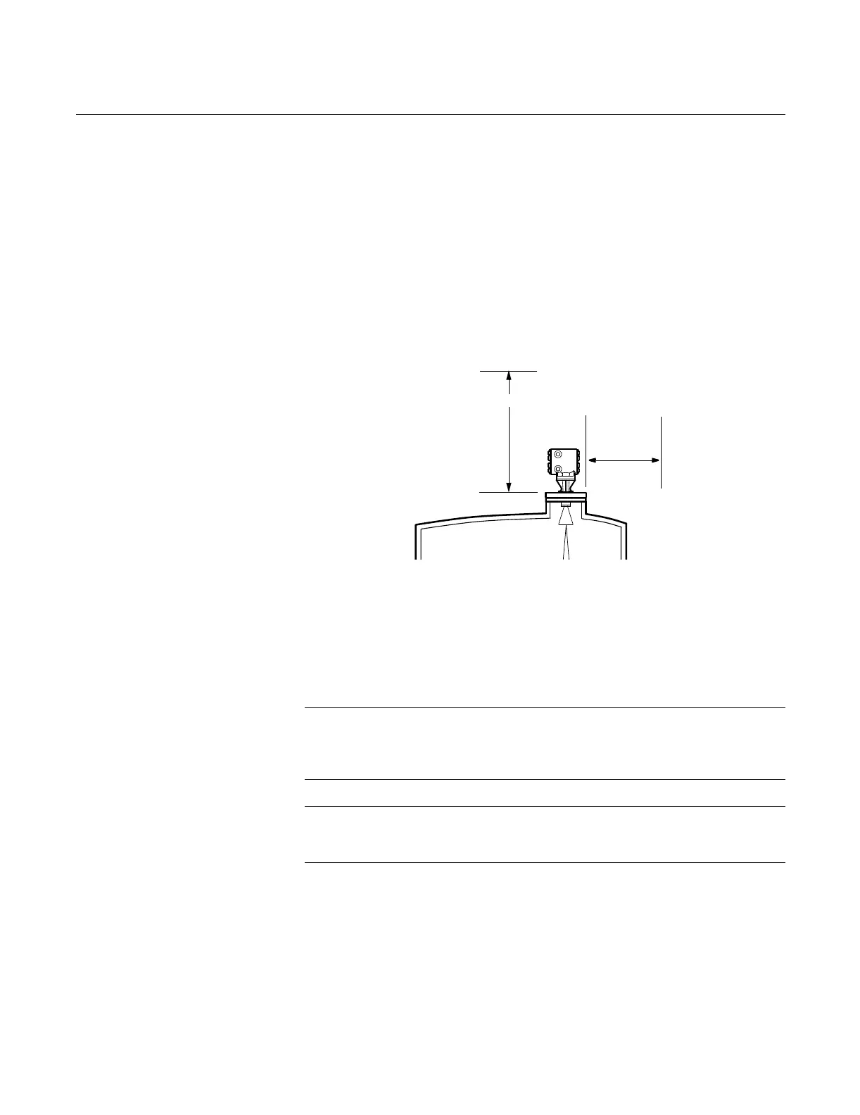
Recommended access clearances for the gauge are shown in Figure 2-16.
Figure 2-16. APEX and APEX
Sentry Radar Gauge Access
Clearances
Wall, Nozzle, or Standoff Clearance
If the radar signal comes in contact with a wall, nozzle, or standoff, it may
cause noise in the level signal. Even though the advanced signal processing
of the radar gauge is designed to filter out this noise, try to keep the noise
level at a minimum by installing the gauge an acceptable distance from
obstructions. To ensure the proper clearance for your vessel height and
beamwidth, review Table 2-2 on page 2-8.
NOTE
When installing an APEX Sentry Radar Gauge, refer to Figure 2-17 on
page 2-21 for further mounting requirements. 100% of the beam cone must
contact the liquid surface for accurate measurement.
NOTE
Do not mount the radar gauge in the top-center of a vessel.
Off-center mounting is preferred.
LEVEL-0005A
18 in. (457mm)
15 in.
(381 mm)