Reference Manual
00809-0100-4731, Rev FA
April 2003
APEX
™
and APEX Sentry
™
Radar Gauge
3-2
BASIC CONFIGURATION
PARAMETERS
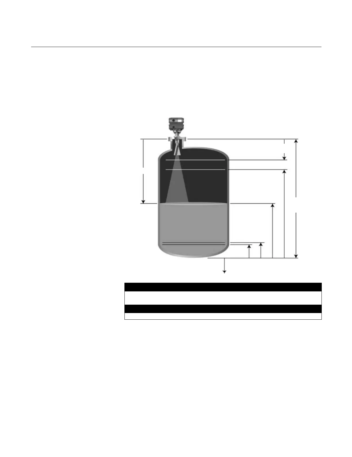
Key Measurement Values
The values given in Figure 3-1 are key factors for installing and configuring
the gauge. Please take a moment to familiarize yourself with the terms used
below. These terms are used throughout this manual.
Figure 3-1. Key Measurement
Values
Reference Gauge Height
The reference line is a common point from which all level measurements are
made. It is usually the bottom of the tank (see Figure 3-1). However, if there is
a stationary object, such as a heat exchanger that is reflective, then that can
serve as the reference line.
Default Values
Upper Null Zone
(1)
(1) See “Null Zones” on page 3-6.
19.6 in (0.5 m)
Lower Null Zone
(1)
-19.6 in (-0.5 m)
Minimum Value
Span (URV-LRV)
(1)
19.6 in (0.5 m)
KEYVALUES.TIF
Reference
Gauge
Height
LRV
(4 mA)
Distance
Empty
Tank
URV
(20 mA)
Upper
Null Zone
APEX or APEX
Sentry Radar
Gauge
Reference
Line
Process
Level
Lower Null
Zone
 Loading...


