Reference Manual
00809-0100-4731, Rev FA
April 2003
2-27
APEX
™
and APEX Sentry
™
Radar Gauge
NOTE
To ensure long life for your radar gauge, and to comply with hazardous
location installation requirements, tighten covers on both sides of the
electronics housing to achieve metal-to-metal contact.
DC Main Power Supply
with No Loop Power
Supply
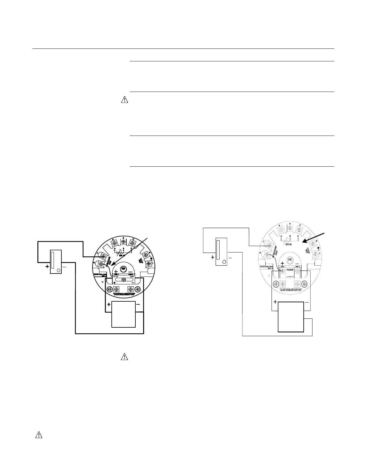
You can also wire the gauge as shown in Figure 2-21, using one 18–36 V dc
power supply capable of supplying 8 watts. Make sure the main power to the
gauge is off and the lines to any other external power source are
disconnected or not powered while wiring the gauge.
NOTE
The APEX draws 1 amp at startup; it is not recommended that a DCS or
channel card be used to power the gauge (the gauge has an operating draw
of 0.375 amp using a 24 vdc supply).
Figure 2-21. DC Power Supply
Connections with no loop power
supply
The power terminals are located under a sliding safety cover on the APEX
terminal block. This sliding cover exposes only one terminal at a time to guard
against electrical shock. The safety cover must be left on while wiring the
APEX gauge. If the cover has been removed, the word “DANGER” appears
near the terminals.
Refer to Safety Messages on page 2-2 for more information.
Indicator/DCS
18–36 V
dc Main
Power
Supply
10.5 W
(fused)
Add Jumper
APEX Radar
Gauge
LEVEL-0033, 3700 1501C01A
APEX Radar Gauge with Output Code 2
or APEX Sentry Radar Gauge
Ground Terminal
18-36 V
dc Main
Power
Indicator/DCS
See note regarding grounding on page 2-23.