• I-1
Index
Numerics
4AO Analog Output Board
features 2-8
4AO Boards 2-8
8DO Boards 2-8
8DO Digital Output Board
defined 2-8
features 2-8
8RO Boards 2-7
8RO Relay Output Board
defined 2-7
features 2-8
8RO/8ROSMT Board 2-7
-A-
ACC 5-34
AHU 5-38
Alarm Information 7-1
Analog Combiner 5-38
Analog Inputs 1-7
Analog Sensor Control 5-3
Anti-Sweat 5-39
case-controlled
how setpoints work 5-39
Application Locations 6-3
Applications 6-3
-B-
Basic Setup 8-1
-C-
Can Bus 1-8
Case Control Circuits 5-40
defrost in 5-42
overview 5-40
Case Controllers
CC-100H
defined 5-41
CC-100LS
defined 5-41
CC-100P
defined 5-41
CS-100
defined 5-41
defrost 5-42
pump down delay 5-43
defrost types 5-43
EEPRs
recovery mode 5-42
recovery mode
EEPRs 5-42
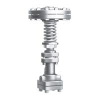
EEVs 5-42
superheat control 5-42
temperature control 5-42
valves 5-41
EEPRs 5-42
EEVs 5-42
liquid pulse 5-42
liquid stepper 5-42
pulse 5-41
stepper 5-41
suction stepper 5-42
CC-100H. See Case Controllers.
CC-100LS. See Case Controllers.
CC-100P. See Case Controllers.
Com Port 4 1-8
Com Ports 1-8
Combiners 5-38
Condenser 5-50
Control Link ACC 5-34
Copeland Digital Discus Compressor 5-1, 5-2
CS-100 5-41
CS-100. See Case Controllers, CS-100
-D-
Data Logging 5-33
Defrost
defrost cycle 5-43
demand 5-43
fail-safe time 5-44
drip time. See Defrost, run-off time.
electric 5-43
emergency 5-44
hot gas 5-43
in case controlled circuits 5-42
inhibiting, using demand sensors 5-43
off-cycle 5-43
pulsed 5-43
pump down delay 5-43
reverse cycle hot gas 5-43
run-off time 5-43
termination 5-43
pulsed defrost 5-43
 Loading...