2.6 Module Footprint
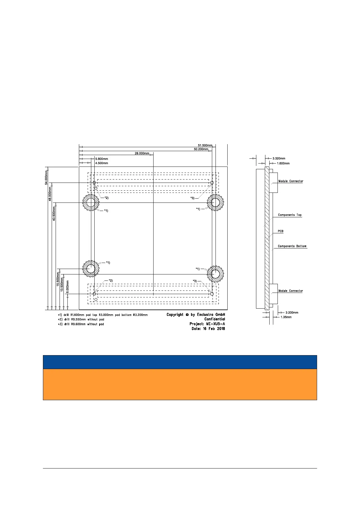
Figure 9 shows the dimensions of the module footprint on the base board.
Enclustra offers Mercury and Mercury+ modules of various geometries having widths of 56, 64, 72 or 74
mm and having different topologies for the mounting holes. If different module types shall be fixed on the
base board by screws, additional mounting holes may be required to accommodate different modules. The
footprints of the module connectors for the base board design are available for different PCB design tools
(Altium, PADS, Eagle, Orcad) [8] and include the required information on the module sizes and holes.
The maximum component height under the module is dependent on the connector type - refer to Section
2.8 for detailed connector information.
Figure 9: Module Footprint - Top View
Warning!
It is possible to mount the Mercury XU5 SoC module the wrong way round on the base board - always
check that the mounting holes on the base board are aligned with the mounting holes of the Mercury
XU5 SoC module.
2.7 Mechanical Data
Table 3 describes the mechanical characteristics of the Mercury XU5 SoC module. A 3D model (PDF) and a
STEP 3D model are available [9], [10].
D-0000-445-001 17 / 64 Version 07, 25.07.2019

 Loading...