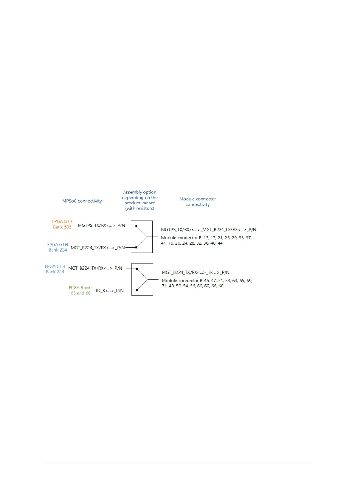
The assembly options affect the MGT connections on connector B (depending mainly on the MPSoC device’s
capabilities) and two pins on connector A, which can be routed to MIO pins (PS side) or to FPGA pins (PL side).
For migration from the Zynq-7000 family modules, Mercury ZX1-30 and Mercury ZX5, to the Zynq Ultra-
scale+ family, the additional “G1” module variants with ZU4 or ZU5 devices can be used. These variants offer
MGT and MIO/FPGA pins (A-82, A-84) compatibility. For ZX1 modules having 8 MGT lines (ZX1-35/ZX1-45
variants), only partial pinout compatibility can be achieved.
The “G1” assembly variants can be also be useful in cases where the end application does not require GTR
transceivers, but instead more regular I/Os.
Design support files such as the Mercury Master Pinout [12], Mercury XU5 SoC Module User Schematics [6],
and Mercury XU5 SoC Module FPGA Pinout Assembly Variants Excel Sheet [5] offer additional information
on assembly options and migration guidelines. In the user schematics, this information is depicted in the
“Assembly Variants” section at the end of the PDF file (MGT_A, MGT_B, MGT_C).
Custom assembly variants are also available. Please contact Enclustra support if none of the standard options
fulfills your system requirements.
Figure 11: Assembly Options for MGT TX/RX Signals
D-0000-445-001 22 / 64 Version 07, 25.07.2019

 Loading...