Symbol Value
Size 56 × 54 mm
Component height top 3.32 mm
Component height bottom 1.35 mm
Weight 26 g
Table 3: Mechanical Data
2.8 Module Connector
Two Hirose FX10 168-pin 0.5 mm pitch headers with a total of 336 pins have to be integrated on the base
board. Up to four M3 screws may be used to mechanically fasten the module to the base board. Do not
use excessive force to tighten the screws, as this could damage the module.
The pinout of the module connector is found in the Mercury Master Pinout Excel Sheet [12]. The connector
is available in different packaging options and different stacking heights. Some examples are presented in
Table 4. Please refer to the connector datasheet for more information.
Reference Type Description
Mercury module connector FX10A-168S-SV Hirose FX10, 168-pin, 0.5 mm pitch
Base board connector FX10A-168P-SV(71) Hirose FX10, 168-pin, 0.5 mm pitch, 4 mm stacking
height
Base board connector FX10A-168P-SV1(71) Hirose FX10, 168-pin, 0.5 mm pitch, 5 mm stacking
height
Table 4: Module Connector Types
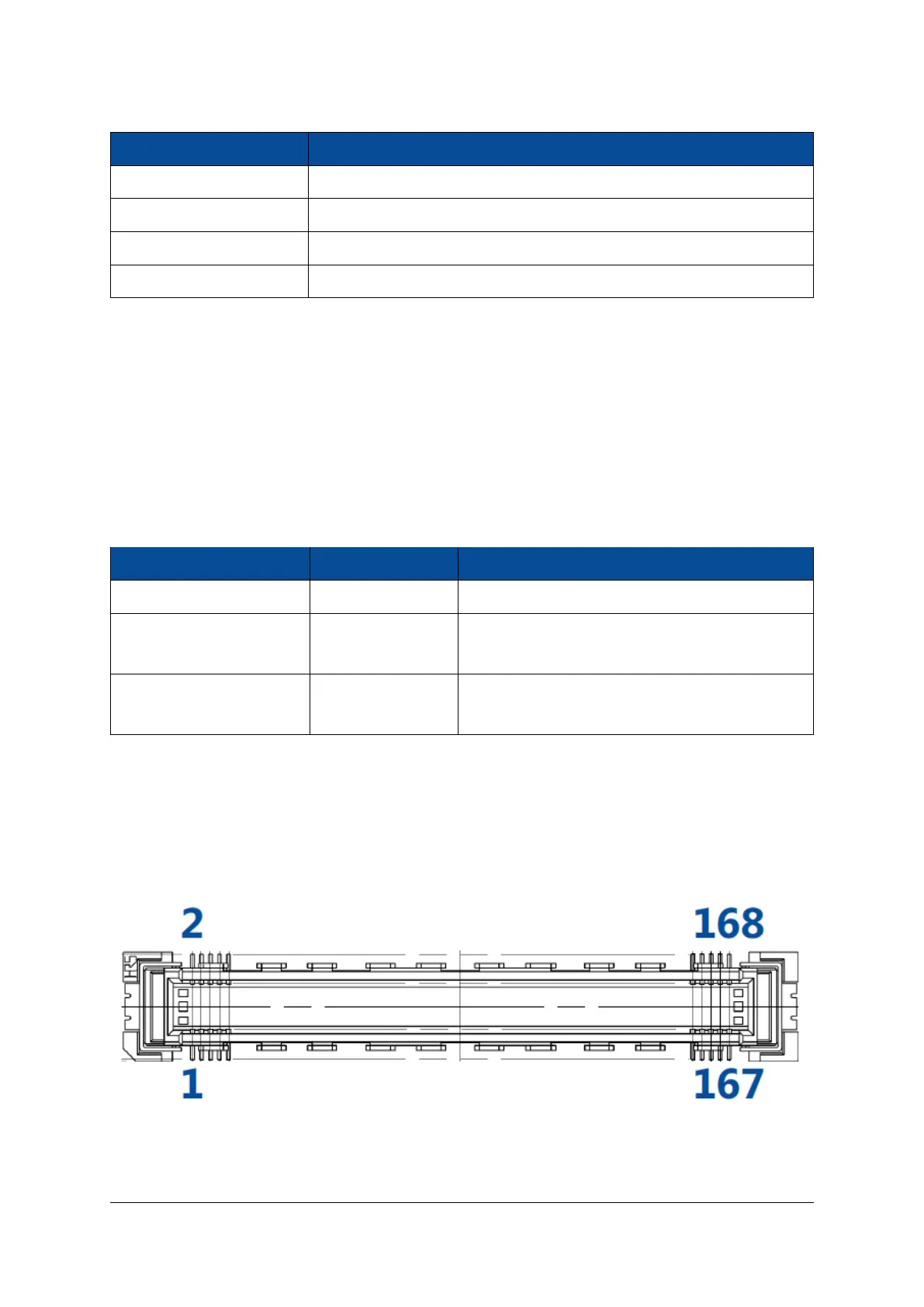
Figure 10 indicates the pin numbering for the Mercury module connectors from the top view of the base
board. The connector pins are numbered as follows:
• Connector A: from J800-1 to J800-168
• Connector B: from J801-1 to J801-168
Figure 10: Pin Numbering for the Module Connector
D-0000-445-001 18 / 64 Version 07, 25.07.2019

 Loading...