4.5 Connecting conductivity sensors
Inductive sensors
Conductivity sensors are connected via
special multi-core, screened measuring cable.
If you need to extend the measuring cables,
use the VBM junction box.
Caution:
Make absolutely sure you protect
plugs and terminals from moisture.
Moisture leads to inaccurate
measuring results!
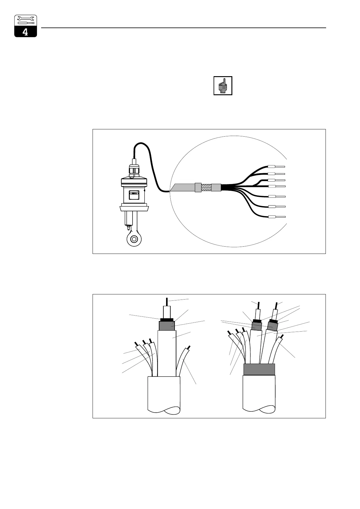
Make-up and termination of measuring cable
white
red
bl
rd
rd
bl
yellow
white
green
11
12
13
anschl52.cdr
Coax inner 14
Coax screen 15
Coax screen 16
Coax inner 17
Fig. 4.24
Inductive sensor
with connecting cable
(here CLS 52)
Semiconductor
screen
Inner conductor
green (11)
white (12)
yellow (13)
(17)
(14)
black
green (11)
white (12)
yellow (13)
brown
(unassigned)
brown
(unassigned)
red
white
(17)
(16)
Semiconductor
screen
Screen
(15)
(14)
CYK 71
CLK 5
KABEL.CDR
Fig. 4.25
Make-up of special
measuring cables
CYK 71 (left) and
CLK 5 (right)
Installation Mycom CLM 152
22 Endress+Hauser

 Loading...


