13 Appendix
13.1 Technical data
13.1.1 Technical data, inductive
Sensor independent data
CLS 50 sensor data
1
) As per IEC 746-1; at rated operating conditions
Measuring range non-compensated
Measuring range compensated
Measurement deviation
1)
±0,5 % of measured value ± 3 digits
Reproducibility
1)
±0,2 % of measured value ± 3 digits
Cable length max. 55 m (with VBM junction box)
Current output transfer characteristic linear, bilinear
Specifications subject to change
General data
Lower measuring range limit
0µS/cm ... 2000 mS/cm
Cell constant 1.98 cm
-1
Storage temperature –20 ... +80 °C
Protection type (DIN 40050) IP 67
Measurement deviation at –20 ... +100 °C
± (5 µS/cm +0.5 % MR)
Measurement deviation > 100 °C
± (10 µS/cm +0.5 % MR)
Temperature measurement
Temperature measurement sensor Pt 100, Class A as per IEC 751
Temperature response time T
90
90 % of final temperature display: 10-15 min (as per DIN 746-1)
Installation
Required pipe cross-section
> DN 80 (for pipe diameters < DN 110, note adaptation factor)
Installation in reduced outflow
≥ DN 50
Supplementary documentation
Technical Information CLS 50 order no. 50090385
Specifications subject to change
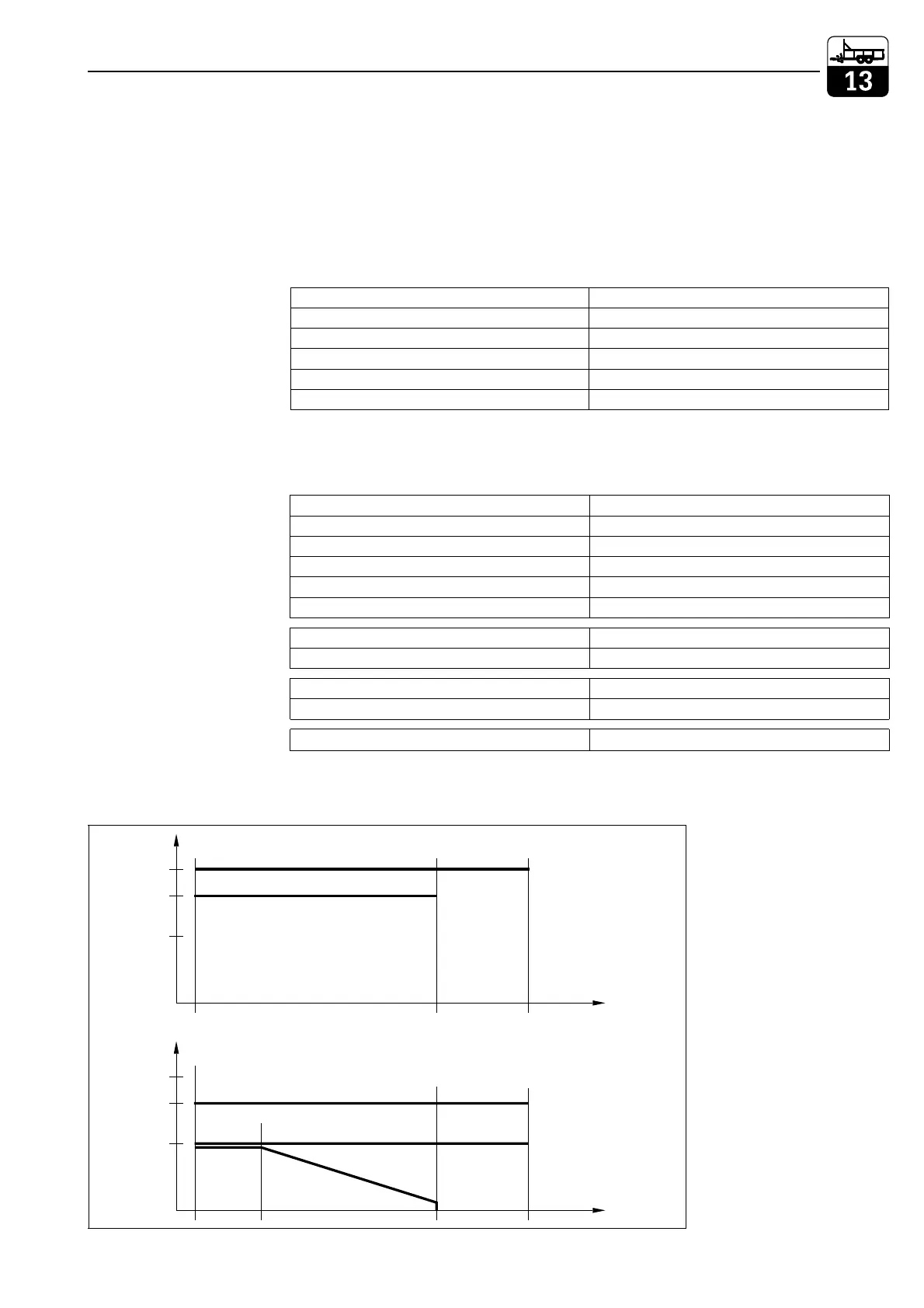
PT-DIAGR.CDR
Order variants
without flange
Order variants
with flange
Pressure
in bar
Pressure
in bar
20
16
10
20
16
10
PEEK
PFA
Variant up to
125 °C
Variant up to
180 °C
–20 20 125 180
–20 125 180
Variant up to
180 °C
Variant up to
125 °C
PVDF
Temperature in °C
Temperature in °C
DN50 / ANSI 2"; stainless
JIS; stainless steel
Fig. 13.1
Pressure vs
temperature curves as
a factor of material
and flange variants
lm152e13.chp
Mycom CLM 152 Appendix
Endress+Hauser 79

 Loading...


