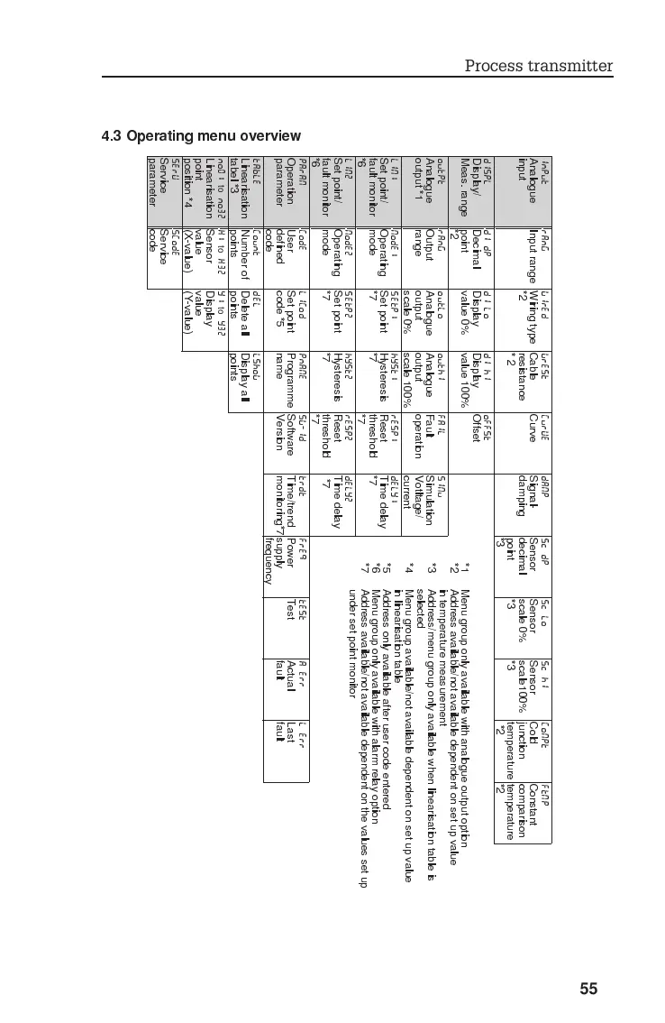
4.3 Operating menu overview
INPUT RANG WIRED WREST CURVE DAMP Sc DP Sc LO Sc HI COMPT FTMP
Analogue
input
Input range Wiring type
*2
Cable
resistance
*2
Curve Signal-
damping
Sensor
decimal
point
*3
Sensor
scale 0%
*3
Sensor
scale100%
*3
Cold
junction
temperature
*2
Constant
comparison
temperature
*2
DISPL DI DP DI LO DI HI OFFST
Display/
Meas. range
Decimal
point
*2
Display
value 0%
Display
value 100%
Offset
OUTPT RANG OUTLO OUTHI FAIL SIMU
Analogue
output *1
Output
range
Analogue
output
scale 0%
Analogue
output
scale 100%
Fault
operation
Simulation
Votltage/
current
LIM1 MODE1 SETP1 HYST1 RESP1 DELY1
Set point/
fault monitor
*6
Operating
mode
Set point
*7
Hysteresis
*7
Reset
threshold
*7
Time delay
*7
LIM2 MODE2 SETP2 HYST2 RESP2 DELY2
Set point/
fault monitor
*6
Operating
mode
Set point
*7
Hysteresis
*7
Reset
threshold
*7
Time delay
*7
PARAM CODE LICOD PNAME SW-ID TRDT FREQ TEST A ERR L ERR
Operation
parameter
User
defined
code
Set point
code *5
Programme
name
Software
Version
Time/trend
monitoring*7
Power
supply
frequency
Test Actual
fault
Last
fault
TABLE COUNT DEL LSHOW
Linearisation
tabel *3
Number of
points
Delete all
points
Display all
points
NO01
to
NO32 X1
to
X32 Y1
to
Y32
Linearisation
point
position *4
Sensor
value
(X-value)
Display
value
(Y-value)
SERV SCODE
Service
parameter
Service
code
*1 Menu group only available with analogue output option
*2 Address available/not available dependent on set up value
in temperature measurement
*3 Address/menu group only available when linearisation table is
selected
*4 Menu group available/not available dependent on set up value
in linearisation table
*5 Address only available after user code entered
*6 Menu group only available with alarm relay option
*7 Address available/not available dependent on the values set up
under set point monitor
Process transmitter
55
 Loading...