Document number: ED.03783.00.001.ENG rev 4 Page 104 of 153
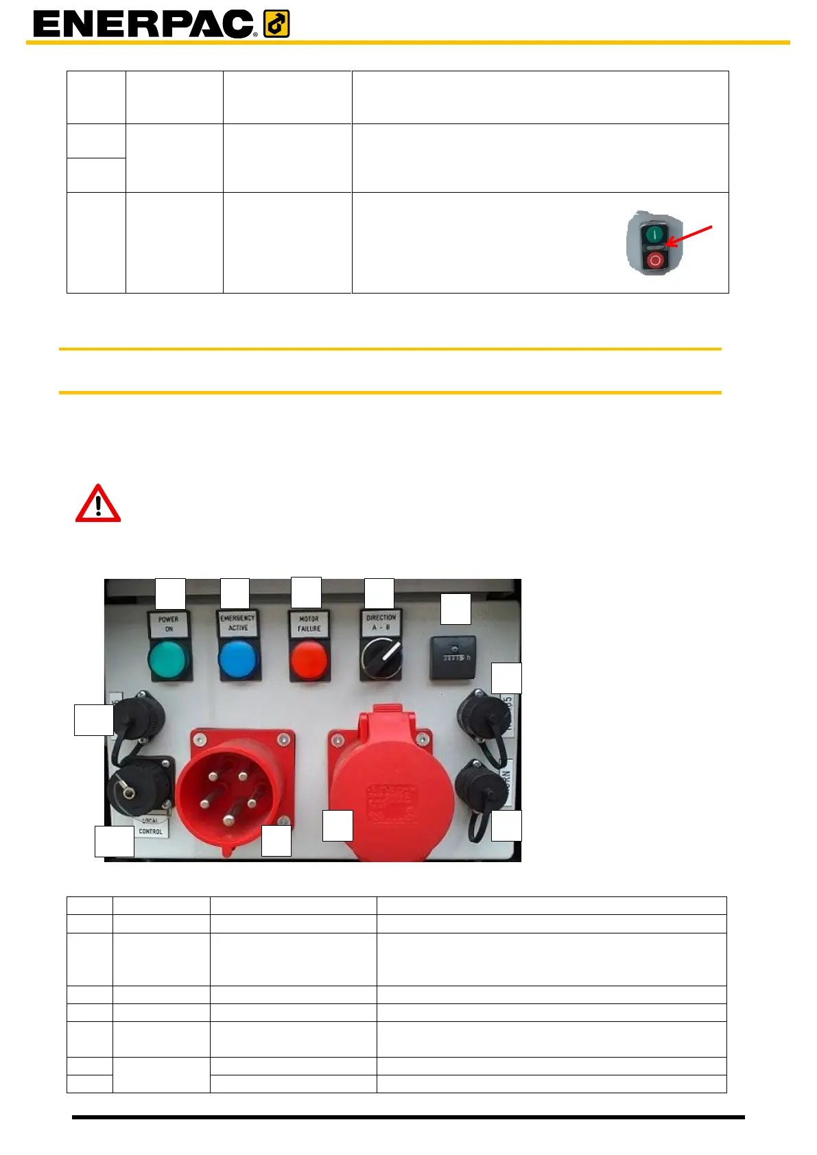
To set the positive travel direction of the unit. Can be
used to mirror the movement of the trolley so they run
in the same direction.
Socket for the data cables, to daisy chain the trolleys
and wire up the remote control.
To switch on the system to an
operational state.
If switched on, the indicator in
between of the buttons is lit.
6.5.2 The JS250
6.5.2.1 The control panel
Each trolley is provided with an electro cabinet. At the front of it is a control panel.
The control panel is intended for setup of the system and for showing errors and statuses.
Attention
Local control is only intended for setting up the system, do not use it when
traveling with load!
The power was switched on by button [11]
Is lit when the emergency button [7] or the
emergency has been pressed. Press the red off
button [11] to recover from an emergency stop.
Is lit when a motor failure occurs.
To set the positie travel direction.
The number of hours the system has been
powered on.
to connect an acoutical alarm device