Document number: ED.03783.00.001.ENG rev 4 Page 71 of 153
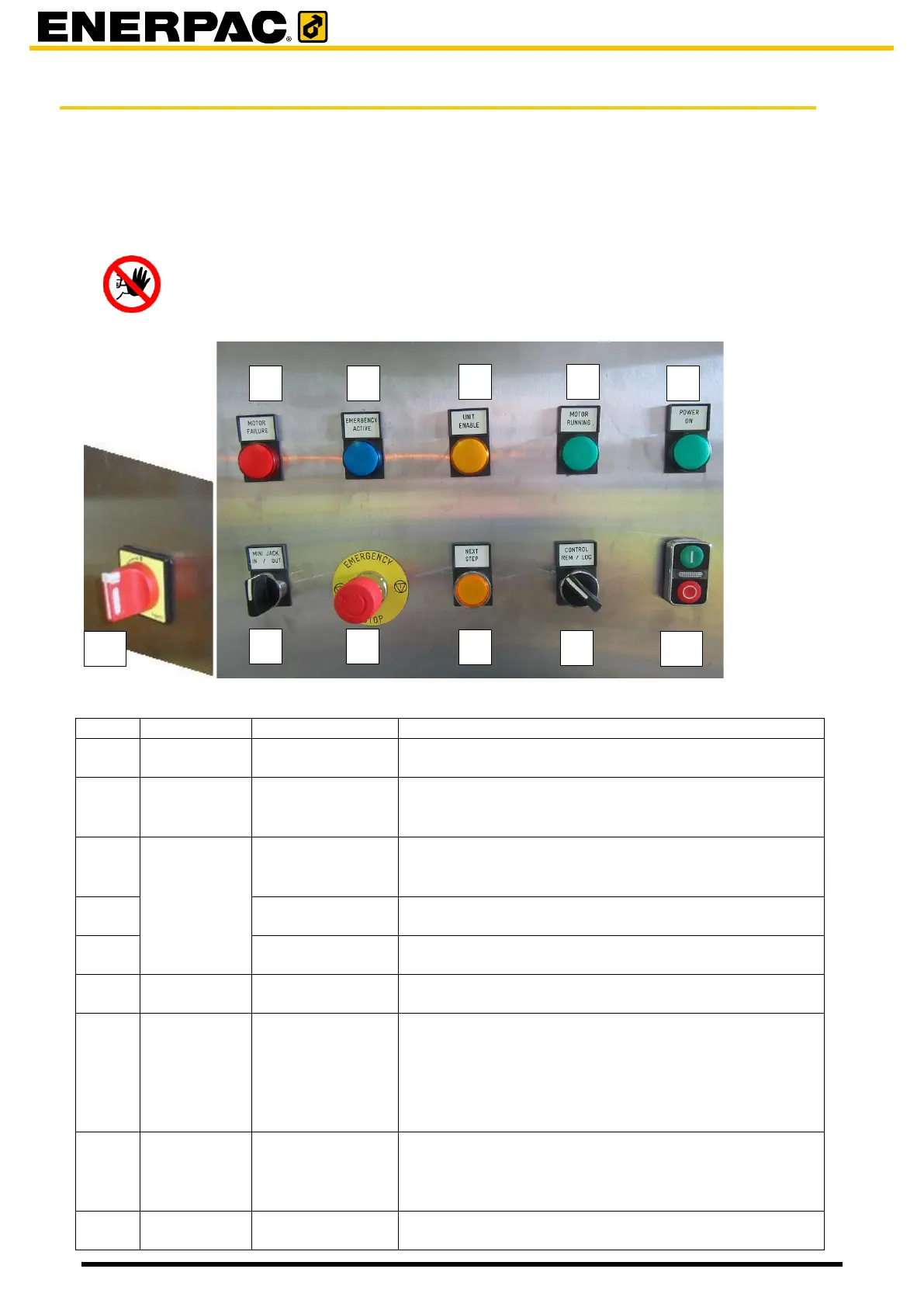
6.2 The control panel on the electro cabinet (JS125 and JS250)
Each unit is provided with an electro cabinet. At the front of it is a controlpanel.
The control panel is intended for
• controlling the unit locally
• showing errors and statuses of the unit.
Hazard
Operating the system locally may causes potential hazards to personnel and
damage to the system, due to the fact that all safety precautions are switched
off.
Is lit when motor failure. The motor has stopped.
Is lit when the emergency button [7] or the emergency
button on the Smartbox has been pressed.
Press the button to recover from an emergency stop.
Is lit when the unit was enabled by the HMI.
When enabled, the unit takes part in the lifting
process.
The motor of the hydraulic system is running
The power was switched on by button [10]
All four mini jacks are extended / retracted
Press in case of emergency. The unit will stop
moving.
When the unit is switched in remote by [6] then other
units which are switched in remote are switched off as
well.
Turn the button to recover from an emergency stop.
Only applicable for automatic mode:
To be pressed by the operator to continue the lifting /
lowering procedure after a barrel has been put in /
removed.
1. When in remote then the unit is controlled by