Document number: ED.03783.00.001.ENG rev 4 Page 103 of 153
6.5 The trolleys
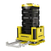
6.5.1 The JS125
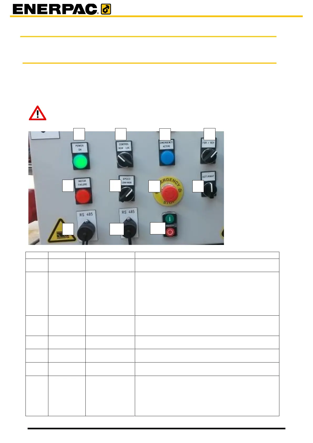
Each trolley is provided with an electro cabinet. At the front of it is a control panel.
The control panel is intended for
• controlling the trolley locally for setup of the system
• showing errors and statuses of the trolley.
Attention
Local control is only intended for setting up the system, do not use it when
traveling with load!
The power was switched on by button [11]
3. When in remote then the unit is controlled by
the remote control. Buttons [4], [6] and [8] do
not apply.
4. When in local, the unit can be controlled from
the control panel for setting up of the system
Is lit when the emergency button [7] or the emergency
has been pressed. Press the red off button [11] to
recover from an emergency stop.
To travel the unit forward and reverse
Is lit when a motor failure occurs.
To set the speed. This in only applicable when the
system is set to local by [2].
Press in case of emergency. The trolley will stop
moving.
When the trolley was in remote as set by [2] then
other trolleys which are switched in remote are
switched off as well.
Turn the button to recover from an emergency stop.