Document number: ED.03783.00.001.ENG rev 4 Page 83 of 153
The Unit name, as set in the window Settings
The mean actual stroke of main jacks
The load on the unit, as calculated from the pressure sensors of the cylinders
Indicator of the total load on the unit.
- yellow = preload
- green = expected load
- red = overload
(Click “Pressure
reading” on the
menu bar to toggle
between the
screens; see
section 6.4.2.6
“Pressure reading”)
The measured stroke of main jacks 1,2,3,4
If text box turns red, the safety switch in the foot of
the main jacks was activated.
The calculated load per cylinder.
The strokes of the main jacks are kept equal
automatically by regulating the pressures of the
individual main jacks. The setpoint fields show the
relative differences of those pressures.
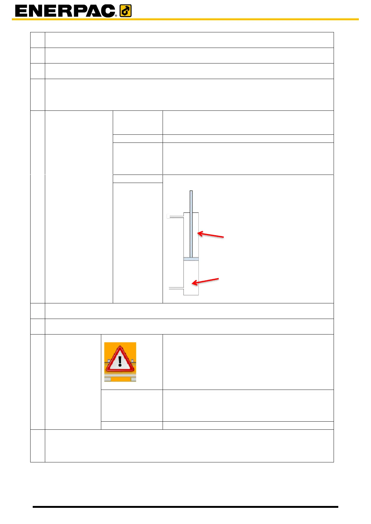
Pressures on the rod side and on the bottom side of
the main jacks:
Pump running indicator ; green when the pump is running
Enable checkbox, to make the unit controllable by the laptop. The unit has to be in remote.
A problem appeared; check the System information
field for the description of the error.
No automatic levelling of the main jacks of this
specific unit is performed.
(It was switched off using the menu bar option
“Hysteresis”, or calibration is active.)
A non-default oil circuit has been configured.
Shows the positions of the mini jacks: extended or retracted.
- Green arrow: the mini jack is retracted
- Red arrow: the mini jack is extended; the barrel is fetched.