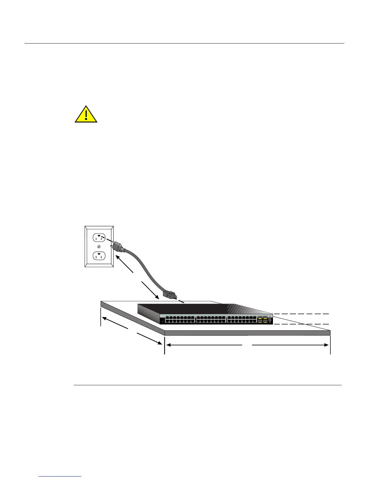
Installing the Switch on a Flat Surface
3-8 Hardware Installation
Guidelines for Flat Surface Installation
Locatetheswitchwithin152cm(5ft)ofitspowersourceandonasurfaceasshownin
Figure 3‐4.Ifanoptionalredundantpowersystemisgoingtobeinstalledandconnected
tothe14‐pinRedundantPowerSupplyinputconnectorontherearoftheswitch,
referto
theinstallationguideshippedwiththeredundantpowersystem.
Ifyouareinstallingseveralswitches inastack,proceedto“Connecting High‐Speed
StackingCables”onpage 3‐10.Iftheswitchisbeinginstalledasastandaloneswitch,
proceedto“ConnectingACand PoEPower”onpage 3‐
15forpowerconnection
instructions.
Figure 3-4 Area Guidelines for Switch Installation on Flat Surface
Caution: To ensure proper ventilation and prevent overheating, leave a minimum
clearance space of 5.1 cm (2.0 in.) at the left, right, and rear of the switch.
Do not connect the switch to the AC power source until instructed to do so later in the
installation process.
Precaución: Para asegurar una buena ventilación y evitar que el sistema
sesobrecaliente, deje un espacio mínimo de 5.1 cm (2 pulgadas) con respecto a los lados
y a la parte posterior del aparato.
1 Approximately 152 cm (5 ft) from power source 3 44.5 cm (19.4 in.) for proper ventilation
2 4.45 cm (1.75 in.) per switch. (Vertical clearance
depends on number of switches stacked.)
4 41.9 cm (16.5 in.) for proper ventilation
Console
1
2
45
CPU
UP
RPS
MGR
DOWN
46
47
48
47
48
C2G124-48P
12345678 910111213141516
15
16
17
18
31
32
33
34
17 18 19 20 21 22 23 24 25 26 27 28 29 30 31 32 33 34 35 36 37 38 39 40 41 42 43 44 45 46 47 48 45 46 47 48
Â
À
Ã
Á