Connecting to the Network
3-22 Hardware Installation
Toconnecttwistedpairsegmentstotheswitch,refertoFigure 3‐13andproceedas
follows:
1. Ensurethatthedevicetobeconnectedattheotherendofthesegmentis
powered ON.
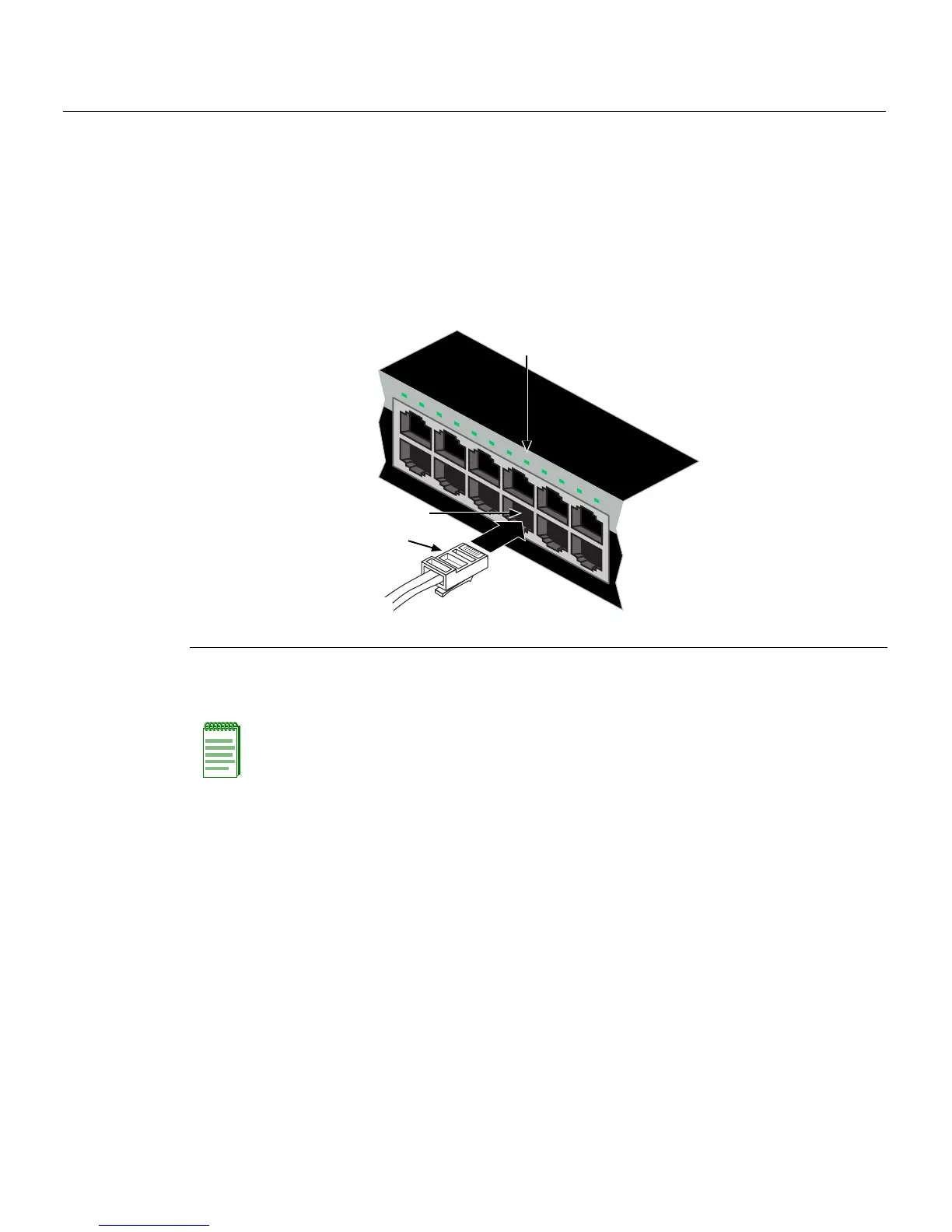
2. Connectthetwistedpair segmenttotheswitchbyinsertingtheRJ45connectoronthe
twistedpairsegmentintothe
desiredRJ45port(forexample,Port8).
Figure 3-13 Connecting a UTP Cable Segment to RJ45 port
3. VerifythatalinkexistsbycheckingthattheLink/ActivityLEDisON(solidgreenor
blinkinggreen)
4. IftheLink/ActivityLEDisOFF,performthefollowingstepsuntilitison:
a. VerifythatthecablingbeingusedisCategory 5orbetterwithan
impedance
between85and111 ohmswithamaximumlengthof100meters(328feet).
b. Verifythatthedeviceattheotherendofthetwistedpairsegmentisonand
properlyconnectedtothesegment.
c. VerifythattheRJ45connectorsonthetwistedpairsegmenthavetheproper
pinoutsandcheck
thecableforcontinuity.Typically ,acrossovercableisused
betweenhubdevices.Astraight‐throughcableisusedtoconnectbetween
switchesorhubdevicesandanenduser(computer).RefertoFigure 3‐14and
Figure 3‐15forfour‐wireRJ45connections.RefertoFigure 3‐16andFigure 3‐17
foreight‐wireRJ45connections.
1 RJ45 connector 2 Port 8 3 Port 8 Link/Activity LED
Note: If the cable is connected to one of the PoE RJ45 front panel ports, solid green or
blinking green also indicates that PoE power is okay. If the LED is solid amber or blinking
amber PoE power failed. For more details, refer to Chapter 4.
1
2
1 2 3 4 5 6 7 8 9 10 11 12
11
12
Â
À
Á