Connecting to the Network
SecureStack C2 Installation Guide 3-29
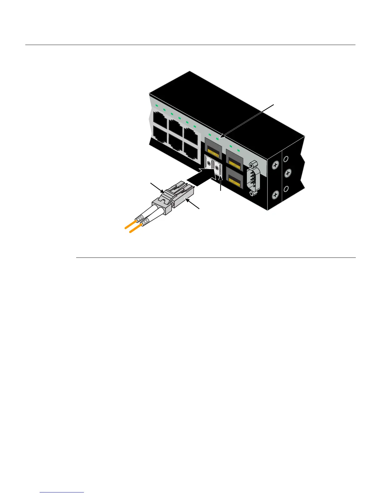
Figure 3-19 Cable Connection to LC Fiber-Optic Connectors
3. Plug theotherendofthecableintotheappropriateportontheotherdevice.Some
cablesmaybeterminatedattheotherendwithtwoseparateconnectors,oneforeach
fiber‐opticstrand.Inthiscase,ensurethat thetransmitfiber‐opticstrandisconnected
tothereceiveport
andthereceivefiber‐opticstrandtothetransmitport.
4. VerifythatalinkexistsbycheckingthattheportLink/ActivityLEDison(blinking
greenorsolidgreen).IftheLink/ActivityLEDisoff,performthefollowingstepsuntil
itison:
a. Verifythatthedeviceatthe otherendof
thesegmentisONandconnectedtothe
segment.
b. Ifthereareseparatefiber‐opticconnectionsontheotherdevice,checkthe
crossoverofthecables. Swapthe cableconnectionsifnecessary.
c. Checkthatthefiber‐opticconnectionmeetsthedBlossandcablespecifications
outlinedintheCablingGuidefor
multimodemodecabling.Toobtainthis
document,referto“RelatedDocuments”onpage xvi.
d. Ifalinkhasnotbeenestablished,refertoChapter 4forLEDtroubleshooting
details.Ifaproblempersists,referto“GettingHelp”onpage 1‐7fordetailson
contactingEnterasys Networksforsupport.
5. Repeatsteps1through
4,above,untilallconnectionshavebeen made.
1 Mini-GBIC MT-RJ port connector 3 Release tab
2 LC cable connector 4 Link/Activity LED
C2G124-24
Console
45
46
47
48
47
C2G124-48P
43 44 45 46 47 48
45 46 47 48
À
Â
Á
Ã