Connecting to the Network
3-26 Hardware Installation
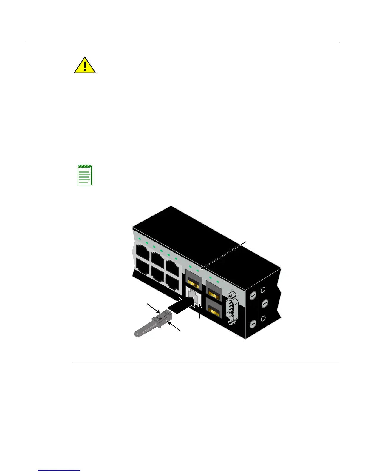
2. InserttheMT‐RJcableconnectorintotheMT‐RJconnectoruntilitclicksintoplace.
Figure 3-18 Cable Connection to MT-RJ Multimode Fiber-Optic Connectors
3. Plug theotherendofthecableintotheappropriateportontheotherdevice.Some
cablesmaybeterminatedattheotherendwithtwoseparateconnectors,oneforeach
fiber‐opticstrand.In
thiscase,ensurethatthetransmitfiber‐opticstrandisconnected
tothereceiveportandthereceive fiber‐opticstrandtothetransmitport.
Caution: Do not touch the ends of the fiber-optic strands, and do not let the ends come in
contact with dust, dirt, or other contaminants. Contamination of cable ends causes
problems in data transmissions. If the ends of the fiber-optic strands become
contaminated, use a canned duster to blow the surfaces clean. A fiber-port cleaning swab
saturated with optical-grade isopropyl alcohol may also be used to clean the ends.
Precaución: No toque los extremos de los cables de fibra óptica y evite su contacto con el
polvo, la suciedad o con cualquier otro contaminante. Si los extremos de los cables se
ensucian, es posible que la transmisión de datos se vea afectada. Si nota que
losextremos de los cables de fibra óptica se ensucian, utilice aire comprimido
paralimpiarlos. También puede limpiarlos con un estropajo embebido en alcohol
isopropílico.
Note: To remove the MT-RJ cable connector, press on its release tab and pull out the
cable connector.
1 Mini-GBIC MT-RJ port connector 3 Release tab
2 MT-RJ cable connector 4 Link/Activity LED
C2G124-24
Console
45
46
47
48
47
C2G124-48P
43 44 45 46 47 48
45 46
47 48
À
Â
Á
Ã