Connecting to the Network
SecureStack C2 Installation Guide 3-21
Whentheseparametersareset,theStartupscreenwilldisplay.Iftheswitchesareina
stackedconfiguration,proceedto“Connecting totheNetwork”onpage 3‐21.
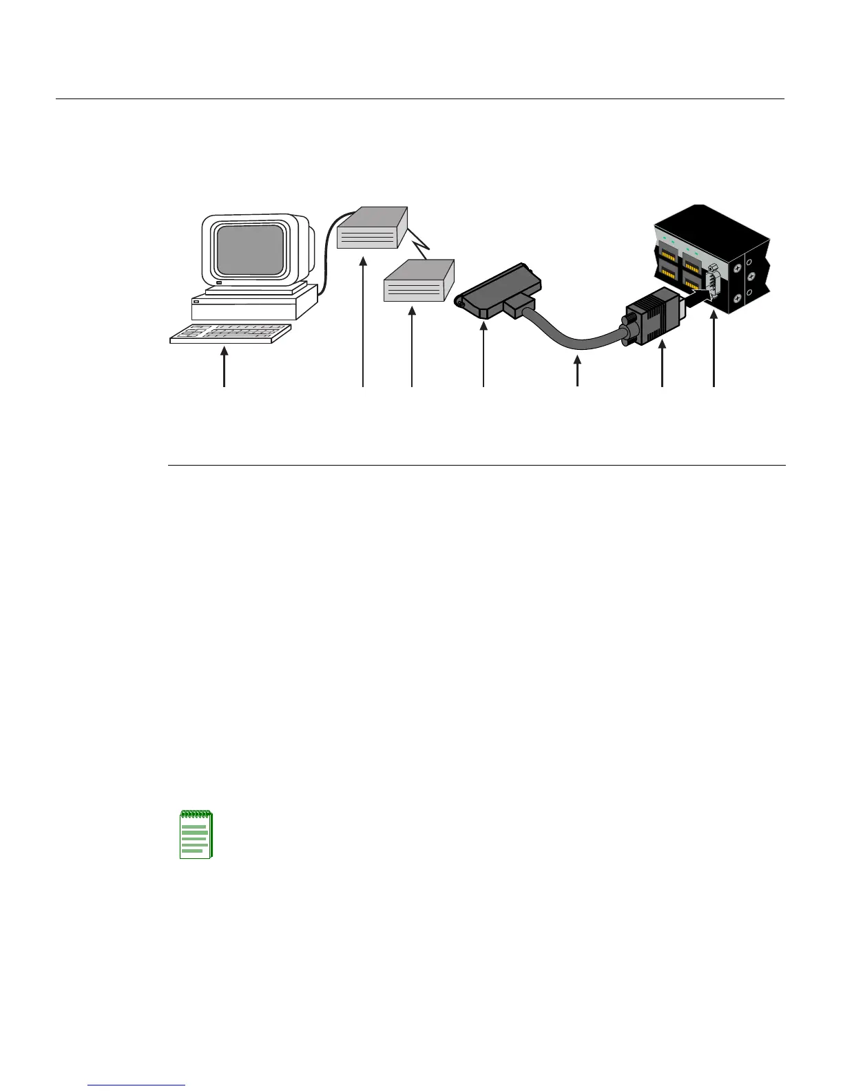
Figure 3-12 Connecting to a Modem
Connecting to the Network
Thefollowingprocedurescoverthecableconnectionsfromthenetworkorotherdevices
totheswitchRJ45portsoranyinstalledoptionalMini‐GBIC.
• ConnectingUTPCablesonpage 3 ‐21
• ConnectingFiber‐OpticCablestoMT‐RJPortsonpage 3‐25
• ConnectingFiber‐OpticCablestoLCPortsonpage 3‐
27
Connecting UTP Cables
ThefixedRJ4 5frontpanelportsare10/100/1000Mbpsportsandhaveinternalcrossovers.
Whenconnectingaworkstationtotheseports,useastraight‐throughcable.When
connectingnetworkingdevicestotheseports,suchasabridge,repeater,orrouter,usea
crossovercable.
1 DB9 female cable connector 4 DB25 male connector 7 PC with VT emulation application
2 Serial interface cable 5 Local modem
3 DB9 male Console port 6 Remote modem
C2G124-24
Console
45
46
47
48
C2G124-48P
45 46
47 48
ÂÃ Á À
ÄÅÆ
Note: All fixed RJ45 front panel ports support Category 5 Unshielded Twisted Pair (UTP)
cabling with an impedance between 85 and 111 ohms. Category 3 cable may be used if
the connection is going to be used only for 10 Mbps.