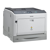
EPSON AcuLaser C9200N Revision D
Troubleshooting Jam Display 104
Confidential
MISFEED AT MP TRAY PAPER FEED SECTION (A, G)
Detection Timing
Action
MISFEED AT CASSETTE 1 PAPER FEED SECTION (A, G)
Detection Timing
Action
Table 3-6. Detection Timing
Type Description
Detection of
Misfeed at MP Tray
Paper Feed section
The leading edge of the paper does not block the Registration Roller
Sensor (PC1) even after the lapse of a given period of time after the MP
Tray Feed Clutch (CL5) has been energized.
MP Tray Paper
Feed section
Loop Registration
Reversing JAM
The Registration Roller Sensor (PC1) is not shaded even when the
specified period of time has passed after the Feed Roller started rotating to
feed paper from MP tray.
Table 3-7. Action
Relevant Electrical Parts
Registration Roller Sensor (PC1)
MP Tray Feed Clutch (CL5)
Mechanical Control Board (PWB-M)
Step Action
Connection Diagram
Control Signal
Location
(electrical parts)
1 Initial check items --- ---
2 PC1 I/O check, Sensor check PWB-M CNSEN-3 (ON) C-3 to 4
3 CL5 operation check PWB-M CNTRY1-2 (ON) C-9
4 Change PWB-M (p.198) --- ---
Table 3-8. Detection Timing
Type Description
Detection of Misfeed at
Cassette 1 Paper Feed
section
The leading edge of the paper does not block the Registration Roller
Sensor (PC1) even after the lapse of a given period of time after the
Cassette 1 Paper Feed Clutch (CL2) has been energized.
Cassette 1 Paper Feed
section
Loop Registration
Reversing JAM
The Registration Roller Sensor (PC1) is not shaded even when the
specified period of time has passed after the Feed Roller started
rotating to feed paper from standard cassette.
Table 3-9. Action
Relevant Electrical Parts
Cassette 1 Paper Feed Clutch (CL2)
Registration Roller Sensor (PC1)
Mechanical Control Board (PWB-M)
Step Action
Connection Diagram
Control Signal
Location
(electrical parts)
1 Initial check items --- ---
2 PC1 I/O check, Sensor check PWB-M CNSEN-3 (ON) C-3 to 4
3 CL2 operation check PWB-M CNLP-13 (ON) C-11
4 Change PWB-M (p.198) --- ---
 Loading...


