EPSON AcuLaser C9200N Revision D
OPERATING PRINCIPLES Operating Principle of Main Unit Mechanism 35
Confidential
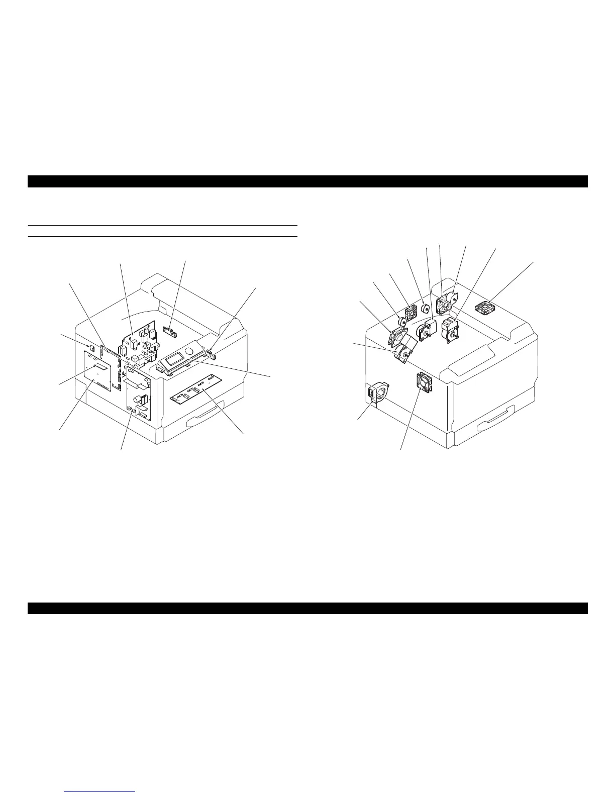
2.2.2 Parts layout drawing
ENGINE SECTION
[1] IDC/Registration Sensor/2 (SE2) [6] Controller Board (PWB-P)
[2] IDC/Registration Sensor/1 (SE1) [7] Program ROM DIMM (WORK0)
[3] Control Panel (PWB-OP) [8] RTC Board (PWB-RTC)
[4] PH Interface Board (PWB-D) [9] Mechanical Control Board (PWB-M)
[5] DC Power Supply (PU1) [10] High Voltage Unit (HV1)
[1] Fusing Drive Motor (M4) [7] Cooling Fan Motor/1 (M12)
[2] Main Motor (M1) [8] Toner Supply Motor Y/M (M6)
[3] Fusing Cooling Fan Motor/2 (M11) [9] Cooling Fan Motor/2 (M22)
[4] Power Supply Cooling Fan Motor/1 (M8) [10] Toner Supply Motor C/K (M7)
[5] Ozone Ventilation Fan Motor (M14) [11] Color PC Drum Motor (M2)
[6] Color Developing Motor (M3) [12] Fusing Cooling Fan Motor/1 (M13)

 Loading...


