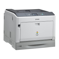
EPSON AcuLaser C9200N Revision D
Troubleshooting Service Call Error 114
Confidential
E200: TRANSFER BELT SEPARATION E210: 2ND TRANSFER ROLLER SEPARATION
E220: TRANSFER BELT UNIT NEW ARTICLE RELEASE
Relevant Electrical Parts
1st Image Transfer Pressure/Retraction
Position Sensor (PC6)
1st Image Transfer Pressure/Retraction
Clutch (CL3)
Main Motor (M1)
Mechanical Control Board (PWB-M)
Step Action
Connection Diagram
Control Signal
Location
(electrical parts)
1 Check the M1 connector for proper
connection and correct as necessary.
--- ---
2 PC6 I/O check, Sensor check --- ---
3 CL3 operation check PWB-M CNDM1-11 (ON) K to L-2
4 M1 operation check PWB-M CNDM1-5 (REM)
PWB-M CNDM1-8 (LOCK)
K to L-2
5 Change PWB-M (p.198) --- ---
Relevant Electrical Parts
Mechanical Control Board (PWB-M) Right Door
Step Action
Connection Diagram
Control Signal
Location
(electrical parts)
1 Check the connector of motor for
proper connection and correct as
necessary.
--- ---
2 Change Right Door (p.260) --- ---
3 Change PWB-M (p.198) --- ---
Relevant Electrical Parts
Mechanical Control Board (PWB-M)
Step Action
Connection Diagram
Control Signal
Location
(electrical parts)
1 Reinstall the Unit. --- ---
2 Change PWB-M (p.198) --- ---
 Loading...


