EPSON AcuLaser C9200N Revision D
APPENDIX Wiring Diagram 343
Confidential
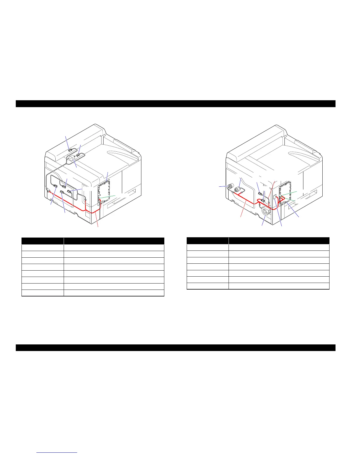
Code Part Name
PWB-M Mechanical Control Board
M5 2nd Image Transfer Pressure/Retraction Motor
PC3 Fusing Loop Detect Sensor
PC7 Lift-up Sensor
PC15 Black PC Drive Main Sensor
PC16 Black PC Drive Sub Sensor
PC17 Color PC Drive Main Sensor
PC18 Color PC Drive Sub Sensor
Code Part Name
PWB-M Mechanical Control Board
PWB-R RTC Board
M14 Ozone Ventilation Fan Motor
CL2 Standard cassette Paper Feed Clutch
CL4 Developing Clutch/K
PC6 1st Image Transfer Pressure/Retraction Position Sensor
PC8 Waste Toner Full Sensor

 Loading...


