EPSON AcuLaser C9200N Revision D
OPERATING PRINCIPLES Other Control 95
Confidential
2.4.2 Engine Section Parts Operated When the Main
Power Switch is Turned ON
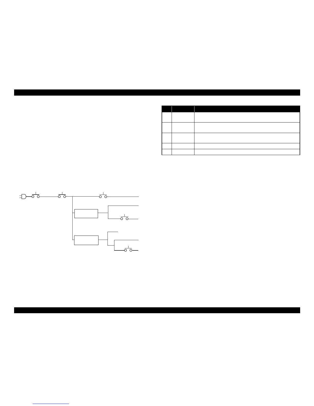
When the Main Power Switch is turned ON, the Mechanical Control Board
detects it and sends a control signal to the DC Power Supply. This turns
ON the Sleep Relay and the DC Power Supply supplies engine section
parts with 3.3 VDC, 5 VDC, and 24 VDC. The Heater Relay is also turned
ON and the Fusing Heater Lamps are supplied with AC power.
If Sleep is activated, the Sleep Relay is turned OFF, thus shutting off power
supply to the engine section. Even when Sleep is activated, DC power
supply to the Controller Board is continued.
If print data is received with the Sleep Relay turned OFF, the relay is
turned ON by the signal provided by the Controller Board and power is
thereby supplied.
No Voltage Connected Parts
1
AC Power
Supply
Heater Lamps
2 DC24V
Fan Motors, Solenoids, Clutches, Erase Lamp, Polygon Motor, 2nd
Image Transfer Pressure/Retraction Motor, MP
3 DC24V
Main Motor, PC Motor, Developing Motor, Fusing Drive Motor, Toner
Supply Motor, Duplex Option, High Voltage Unit
4 DC5V CPU, ADC, Sensors, Control Panel
5 DC5V Power supply to board

 Loading...


