EPSON Perfection V10/V100 Photo/V200 Photo/V350 Photo Revision B
DISASSEMBLY/ASSEMBLY Disassembly Procedure 33
4.2 Disassembly Procedure
This section illustrates how to remove the main components of this product. Unless otherwise specified, the reassembly procedure is the reverse of the disassembly procedure. For
additional assembly illustrations, refer to the exploded diagrams provided by SPI (Service Parts Information).
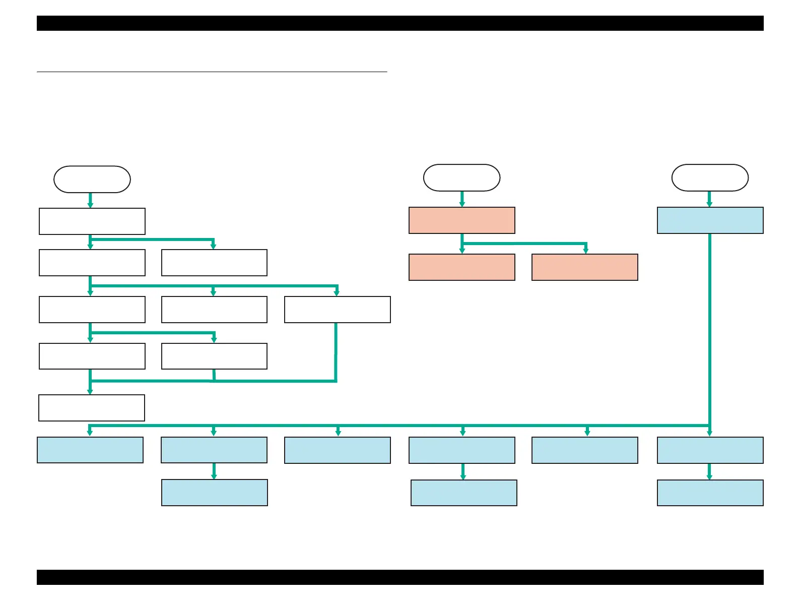
The following flowchart shows the disassembling procedure step-by-step. When disassembling any unit, refer to the corresponding page number shown in the following figure.
Figure 4-1. Perfection V10/V100 Photo/V350 Photo Disassembly/Reassembly Flowchart
Document Cover(P.35)
Upper Housing(P.35)
Carriage Unit(P.41)
CR Motor(P.39)
Main Board(P.37)
Hinge(P.36)
Driven Pulley(P.41)
Harness TPU/TPU Inverter
Board(P.44)
Panel Board(P.37)
Lamp Assy(P.45)
Harness AFL/AFL Main
Board(P.47)
Separation of AFL Upper
Housing Assy/AFL Lower
Housing Assy(P.46)
Start
Disassembly of Main Unit
Start
Start
Disassembly of TPU
(Perfection V100 Photo/V200 Photo)
Disassembly of AFL
(Perfection V350 Photo)
TPU Upper Housing(P.43)
AFL Inverter Board/AFL
Inverter Board Cover(P.48)
Film Ejection Cover(P.51)
Cover Lower Assy/AFL
Sensor A(P.51)
AFL Sensor B(P.50)
Film Holder Lock(P.54)
Damper/Film Holder(P.53)
Eject Button(P.55)
Lamp Assy(P.49)
Hinge Disengagement(P.34)
 Loading...