EPSON Perfection V10/V100 Photo/V200 Photo/V350 Photo Revision B
OPERATING PRINCIPLES Engine Operation Outline 18
2.1 Engine Operation Outline
This section explains the functions and operating principles of the Perfection V10/
Perfection V100 Photo/Perfection V200 Photo/Perfection V350 Photo.
2.1.1 Outline
CARRIAGE UNIT OUTLINE
(PERFECTION V10 / V100 PHOTO / V200 PHOTO / V350 PHOTO)
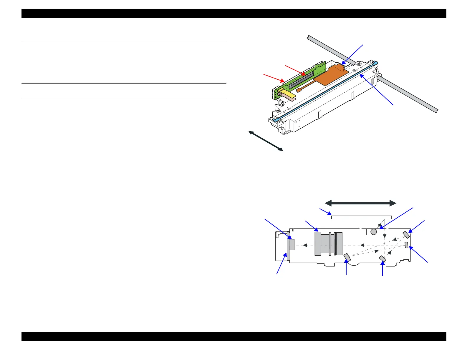
The Carriage Unit consists of the CCD Board, Inverter Board, Lamps (light source)
and Mirror/Lens Mechanism. (Refer to Figure 2-1 and 2-2.)
CCD Board
The Board consists of a CCD (loaded with a six-lines CCD microlens) and its
control and drive circuits.
Inverter Board
Boosts +24VDC and converts DC to AC to generate the voltage for driving the
Lamp (white cool cathode fluorescent lamp).
Lamps
White cool cathode fluorescent lamp (1 piece: for reflective document) is used as a
light source.
Mirror/Lens Mechanism
The beam applied to the scanned document is reflected, passes through the Mirror/
Lens Mechanism in the Carriage Unit for correction of the beam axis, and then
reaches the CCD Sensor. The light components R, G, B are extracted by the Color
CCD Sensor itself.
Figure 2-1. Carriage Unit Configuration
Figure 2-2. Mirror/Lens Mechanism
CCD Board
Inverter Board
CCD Sensor
Lamp
Front
Rear
Front
Rear
Lamp
Document
Mirror 1
Mirror 2
Mirror 4
CCD Sensor
CCD Board
Lens
Mirror 3
 Loading...