EPSON Perfection V10/V100 Photo/V200 Photo/V350 Photo Revision B
APPENDIX Connector Configuration 63
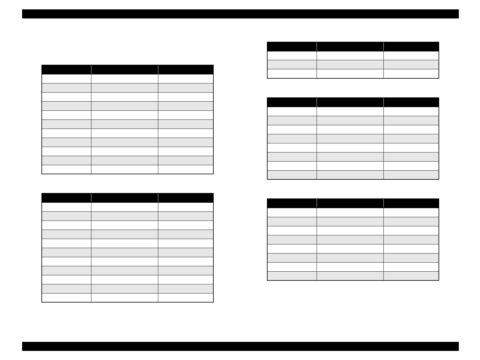
7.1.3 Connection Table
The following tables are connection tables of connectors on the respective boards.
Note"*1": Perfection V10
"*2": Perfection V100 Photo/V350 Photo
"*3": Perfection V200 Photo
Note"*": Perfection V350 Photo
Table 7-4. Main Board CN1-CCD Board
Pin No. Signal I/O
1 GND
-
2 3.3V
O
3D6
I
4 D4
I
5D2
I
6 DO
I
7TG
I
8 GND
-
9 SDEN8
I
10 RESET8
I
11 13.5V
O
Table 7-5. Main Board CN2-CCD Board
Pin No. Signal I/O
1 GND
-
2 5.12V*
1
/VCC*
2
/5.17V*
3
O
3 GND
-
4 ADCK
O
5 GND
-
6 D1
I
7D3
I
8 D5
I
9D7
I
10 INV_GND
-
11 L13.5V
O
Table 7-6. Main Board CN3-AC Input
Pin No. Signal I/O
1 13.5VDC
I
2 GND
-
3GND
-
Table 7-7. Main Board CN4-PNL Board
Pin No. Signal I/O
1OP-LED
O
2 ERR-LED
O
3 PUSH-SW3
I
4 PUSH-SW2
I
5 PUSH-SW4
I
6 PUSH-SW1
I
7GND
-
8 3.3V
O
Table 7-8. Main Board CN5-AFL Main Board
Pin No. Signal I/O
1Vcc
O
2 GND
-
3SCK
O
4 TXD
O
5LOD
O
6 RXD
O
7TPU_GND
O
8 +13.5V
O
 Loading...