EPSON Perfection V10/V100 Photo/V200 Photo/V350 Photo Revision B
APPENDIX Connector Configuration 62
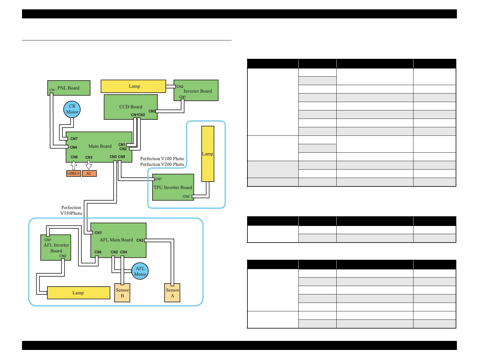
7.1 Connector Configuration
The wiring assembly of the connectors on the major circuit board are shown below.
7.1.1 Connector Configuration
Figure 7-1. Diagram of Wiring Connectors
7.1.2 Connector Connection Table
Note *1: Perfection V350 Photo
*2: Perfection V100 Photo/V200 Photo
Table 7-1. The Main Unit Connection Table
(Perfection V10/V100 Photo/V200 Photo/V350 Photo)
Board Connector Description Number of Pins
Main Board
CN1
CCD Board 11
CN2
CN3 AC Input 3
CN4 PNL Board 8
CN5*
1
AFL Main Board 8
CN6 USB Connector 4
CN7 CR Motor 4
CN8*
2
TPU Inverter Board 2
CCD Board
CN1
Main Board 11
CN2
CN3 Inverter Board 2
Inverter Board
CN1 CCD Board 2
CN2 Lamp 2
Panel Board CN1 Main Board 8
Table 7-2. The TPU Connection Table (Perfection V100 Photo/V200 Photo)
Board Connector Description Number of Pins
TPU Inverter Board
CN1 Main Board 2
CN2 Lamp 2
Table 7-3. The AFL Connection Table (Perfection V350 Photo)
Board Connector Description Number of Pins
AFL Main Board
CN1 Main Board 8
CN2 AFL Motor 4
CN3 Sensor A 3
CN4 Sensor B 3
CN6 AFL Inverter Board 2
AFL Inverter Board
CN1 AFL Main Board 2
CN2 Lamp 2
 Loading...