EPSON Perfection V10/V100 Photo/V200 Photo/V350 Photo Revision B
DISASSEMBLY/ASSEMBLY Disassembly of Main Unit 38
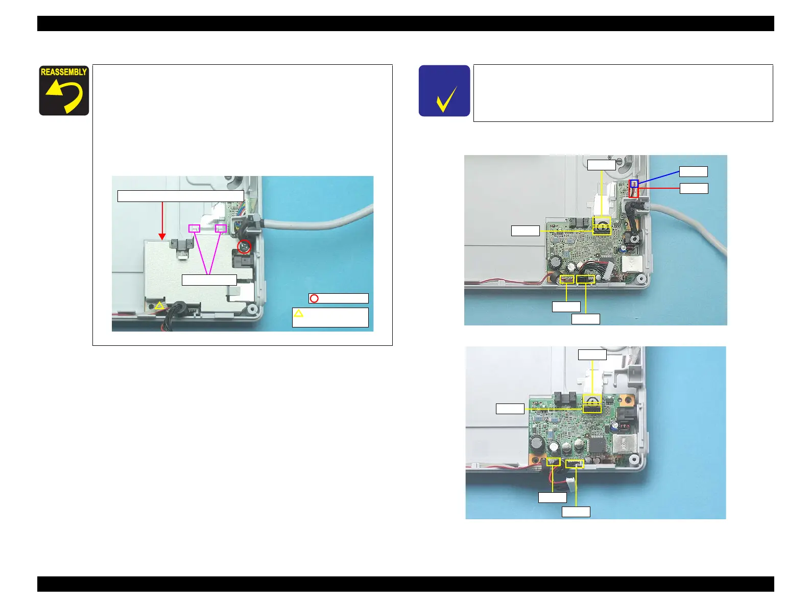
5. Disconnect CN1, CN2, CN4, CN7 connectors, and CN5 for the V350 Photo, and
CN8 for the Perfection V100 Photo/V200 Photo to remove the Main Board.
Figure 4-12. Removing the Main Board (Perfection V100 Photo/V200 Photo/V350 Photo)
Figure 4-13. Removing the Main Board (Perfection V10)
When reassembling the Upper Main Board Shield Plate, match
the guide pin and the positioning hole, and insert the plate
under the Lower Main Board Shield Plate.
For the Perfection V100 Photo/V200 Photo/V350 Photo, make
sure to screw the Upper Main Board Shield Plate together with
the earth cable of the Harness TPU/Harness AFL.
When reassembling the Upper Main Board Shield Plate, be
careful not to get the CR Motor cable caught under the plate.
Figure 4-11. Reassembling the Upper Main Board Shield Plate
Guide pin and
positioning hole
C.B.P. 3x8
Upper Main Board Shield Plate
Insert position
C H E C K
P O I N T
Perfection V10 is equipped with a different Main Board to
Perfection V100 Photo/V350 Photo, therefore note that the number
of connectors differ.
CN1
CN2
CN4
CN7
CN5
CN8
CN4
CN7
CN1
CN2
 Loading...