EPSON Stylus CX4300/CX4400/CX5500/CX5600/DX4400/DX4450 Revision A
APPENDIX Connector Summary 116
7.1 Connector Summary
7.1.1 Major Component Unit
Main Board
Power Supply Board
Panel Board
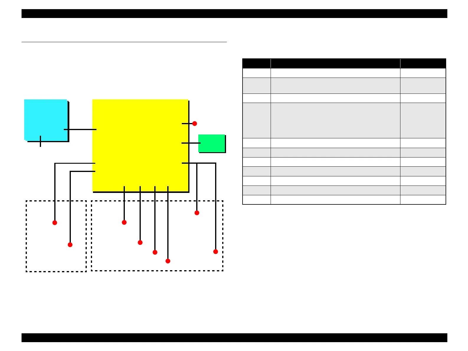
Figure 7-1. Connection of the major components
See the following tables for the connector summary of the Main Board and each
connector’s pin assignment.
Main Board
J9
J1
Power Supply
Board
AC power
Printer
Mechanism
USB I/F
J5
J6
CIS Assy.
Scanner Motor
Scanner
Mechanism
PE Sensor
CN1
Printhead
J7
CR Motor
J3
J8
PF Motor
Panel
Board
J2
CN2
CR Encoder
Sensor
CSIC Board
Table 7-1. Connector Summary for Main Board
Connector
Function Table to refer to
CN1 For connection with the Printhead Table 7-2 (p.117)
CN2
For connection with the CR Encoder Sensor
and the CSIC Board.
Table 7-3 (p.117)
J1 For connection with the Power Supply Board Table 7-4 (p.117)
J2 For connection with the USB interface
“ The printer has a
USB interface of
the following
specification.”
(p.19)
J3 For connection with the Panel Board Table 7-5 (p.118)
J4 Not used N/A
J5 For connection with the CIS Assy. Table 7-6 (p.118)
J6 For connection with the Scanner Motor Table 7-7 (p.118)
J7 For connection with the CR Motor Table 7-8 (p.118)
J8 For connection with the PF Motor Table 7-9 (p.118)
J9 For connection with the PE Sensor Table 7-10 (p.118)

 Loading...


