EPSON Stylus CX4300/CX4400/CX5500/CX5600/DX4400/DX4450 Revision A
OPERATING PRINCIPLES Electrical Circuit Operating Principles 30
2.4 Electrical Circuit Operating Principles
The electric circuit of Stylus CX4300/CX4400/CX5500/CX5600/DX4400/DX4450
consists of the following boards:
Main board: PCBA MB
Power supply board: ASSY POWER 110V/220V
Panel board: PCBA PB
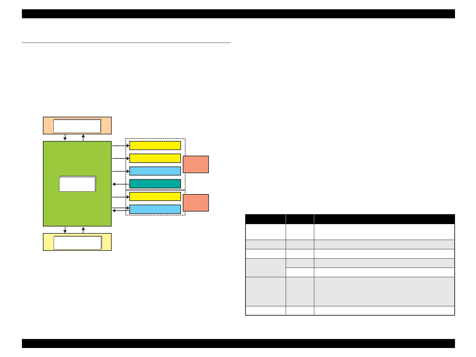
The figure below shows the block diagram of this printer.
Figure 2-7. Electrical Circuit Block Diagram
2.4.1 Power Supply Board
In the Power Supply Board of Stylus CX4300/CX4400/CX5500/CX5600/DX4400/
DX4450, the simulated oscillating stimulation flyback converter circuit method is
used, and it supplies +42 VDC to the drive line. The application of the output voltage is
described below.
AC voltage input from AC inlet first goes through filter circuit that removes high
frequency components and is then converted to DC voltage via the rectifier circuit and
the smoothing circuit. DC voltage is then led to the switching circuit and FET QF1
preforms the switching operation. By the switching operation of the primary circuit,
+42VDC is generated and stabilized at the secondary circuit.
2.4.2 Main Board
The logic circuit of the Main Board is composed of the following:
Logic line (CPU-ASIC 4 in 1, Flash-ROM and so on)
Motor control/drive circuit (CR Motor, PF Motor, Scanner Motor)
Head control/drive circuit
USB I/F circuit
Sensor circuit
Reset circuit, EEPROM circuit
Main Board
Power Supply Board
Sensors
Head Driver Board
PF Motor
CR Motor
Printer
Mechanism
+42VDCPower Off
Panel Board
Scanner
Mechanism
Scanner Motor
CIS Assy.
Table 2-5. Main Board Major Components and Primary Functions
IC Location Function
CPU-ASIC U3
Drives CPU (H8S/2674 base), internal 8 K byte x 4 RAM,
24 Mhz, 3.3 V/1.8V
SDRAM U4 3.3 V drive 4M x 16 bit DRAM
Serial Flash U5 3.3 V drive 4 M bit Serial Flash that stores the program
Motor Driver
U6 Scanner motor drive; adjusts 5 V, drives 42 V
U7 CR/PF motor drive; adjusts 5 V, drives 42 V
RTC U9
•EEPROM
Default settings, backup for all parameters
• Reset function
• Timer function
DAC U10 Generates trapezoidal waveform, drives 3.3 V

 Loading...


