EPSON Stylus CX4300/CX4400/CX5500/CX5600/DX4400/DX4450 Revision A
DISASSEMBLY/ASSEMBLY Disassembling Printer Mechanism 87
4.6.9 Main Frame
Part/Unit that should be removed before removing LD Roller/ASF Unit
Document Cover / ASF Cover / Support Arm / Scanner Unit / Middle Case /
Panel Unit / Printer Mechanism / Hopper / Main Board / Print Head / CR Scale /
CR Motor / CR Unit / Timing Belt
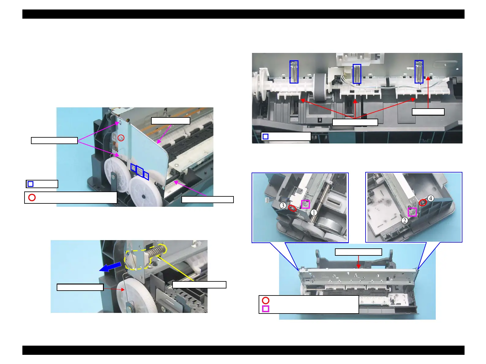
Removal procedure
1. Remove the screw and the Grounding Spring, and remove the Shield Plate L
while releasing the hooks and the positioning holes.
Figure 4-66. Removing Shield Plate L
2. Remove the PF Roller Grounding Spring.
3. Remove the Driven Pulley Holder from the notch of the Main Frame.
Figure 4-67. Removing Grounding Spring and Driven Pulley Holder
4. Remove the Extension Springs (x3) from the hooks of the Main Frame and the
guide pins of the Upper Paper Guide.
Figure 4-68. Removing Extension Springs
5. Remove the screws (x4) that secure the Main Frame to the Frame Base.
Figure 4-69. Removing Main Frame (1)
Grounding Spring
C.B.S 3X6 (Torque: 6±1Kgf.cm)
Hooks
Shield Plate L
Positioning Hole
Grounding Spring
Driven Pulley Holder
Main Frame
Extension Springs
Upper Paper Guide
Main Frame
C.P 3X4 (Torque: 4±1Kgf.cm)
C.B.S-(P2) 3X6 (Torque: 8±1Kgf.cm)

 Loading...


