EPSON Stylus CX4300/CX4400/CX5500/CX5600/DX4400/DX4450 Revision A
TROUBLESHOOTING Overview 33
3.1 Overview
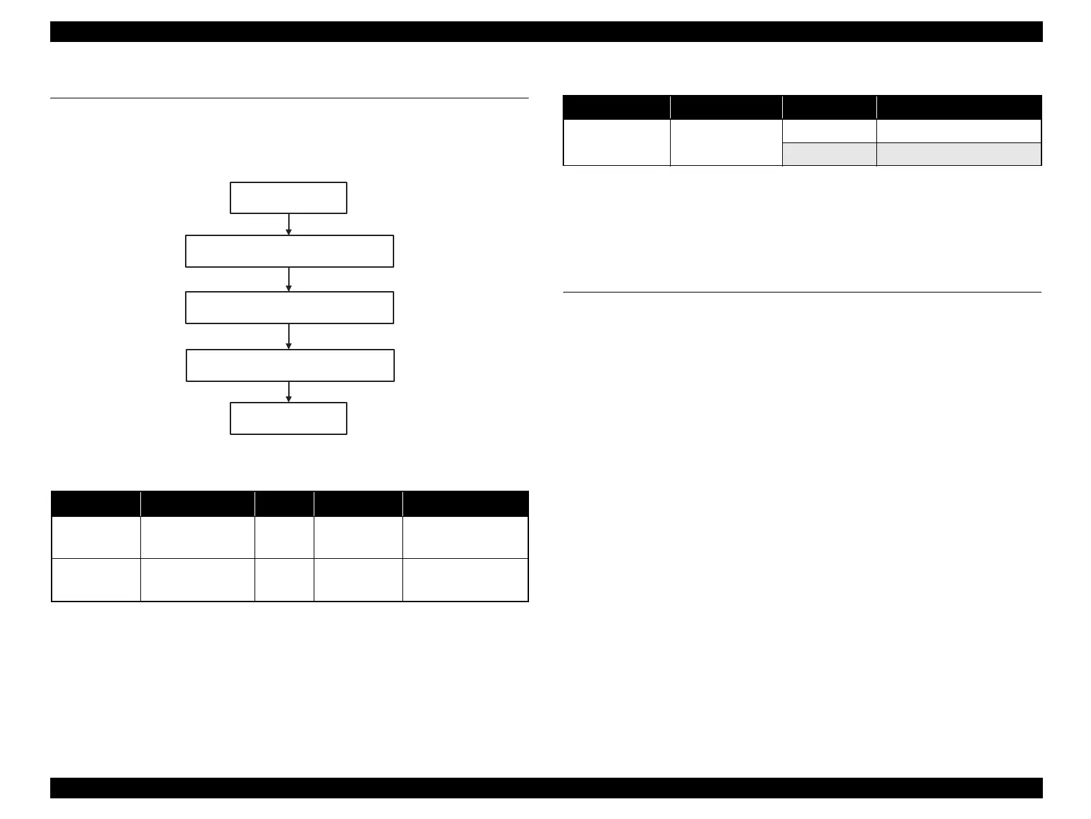
This chapter describes unit-level troubleshooting. Refer to the flowchart in this chapter
to identify the defective unit and perform component level repair if necessary. This
chapter also explains motor coil resistance, sensor specification and error indication.
Figure 3-1. Troubleshooting flowchart
Note : The CR motor is DC motor. Since the resistance of the DC motor varies among the
electric poles, resistance value cannot be used to check the DC motor. When a
malfunction of the CR motor is suspected, check the motor if it moves normally or not.
However, it is difficult to judge accurately, if it is not clear, replace the motor.
3.2 Error Indications and Fault Occurrence
Causes
This section describes the LED indications, STM3 messages and fault occurrence
causes at occurrence of the following errors during any sequence/operation (e.g.
power-on sequence, paper feeding/loading sequence, ink sucking sequence).
NOTE: The STM3 windows shown in the table in the following pages are the
ones of Stylus CX4300/CX4400/CX5500/CX5600/DX4400/DX4450,
however, other models show almost the same displays as those except the
following items:
1) Printer model name
2) T-code for each ink cartridge (refer to
Table 1-3 (p.10) )
Table 3-1. Motor, coil resistance
Motor Motor Type Location Check point Resistance
Scanner motor Stepping motor J6
Pin 1 and 3
Pin 2 and 4
37Ω ± 10% (T.B.D.)
PF motor
4-phase, 48-pole,
PM Stepping motor
J8
Pin 1 and 3
Pin 2 and 4
4.3Ω+8/-12% (20°C)
START
Unit-level troubleshooting
Unit repair
Assemble & Adjustment
END
Table 3-2. Sensor check point
Sensor name Check point Signal level Switch mode
PE Sensor J9 / Pin 1 and 2
Less than 0.4V Off: No paper
More than 2.4V On : Detect the paper

 Loading...


