EPSON Stylus CX4300/CX4400/CX5500/CX5600/DX4400/DX4450 Revision A
DISASSEMBLY/ASSEMBLY Disassembling Printer Mechanism 78
4.6.2 Hopper
Part/Unit that should be removed before removing Hopper
Document Cover / ASF Cover / Support Arm / Scanner Unit / Middle Case /
Panel Unit / Printer Mechanism
Removal Procedure
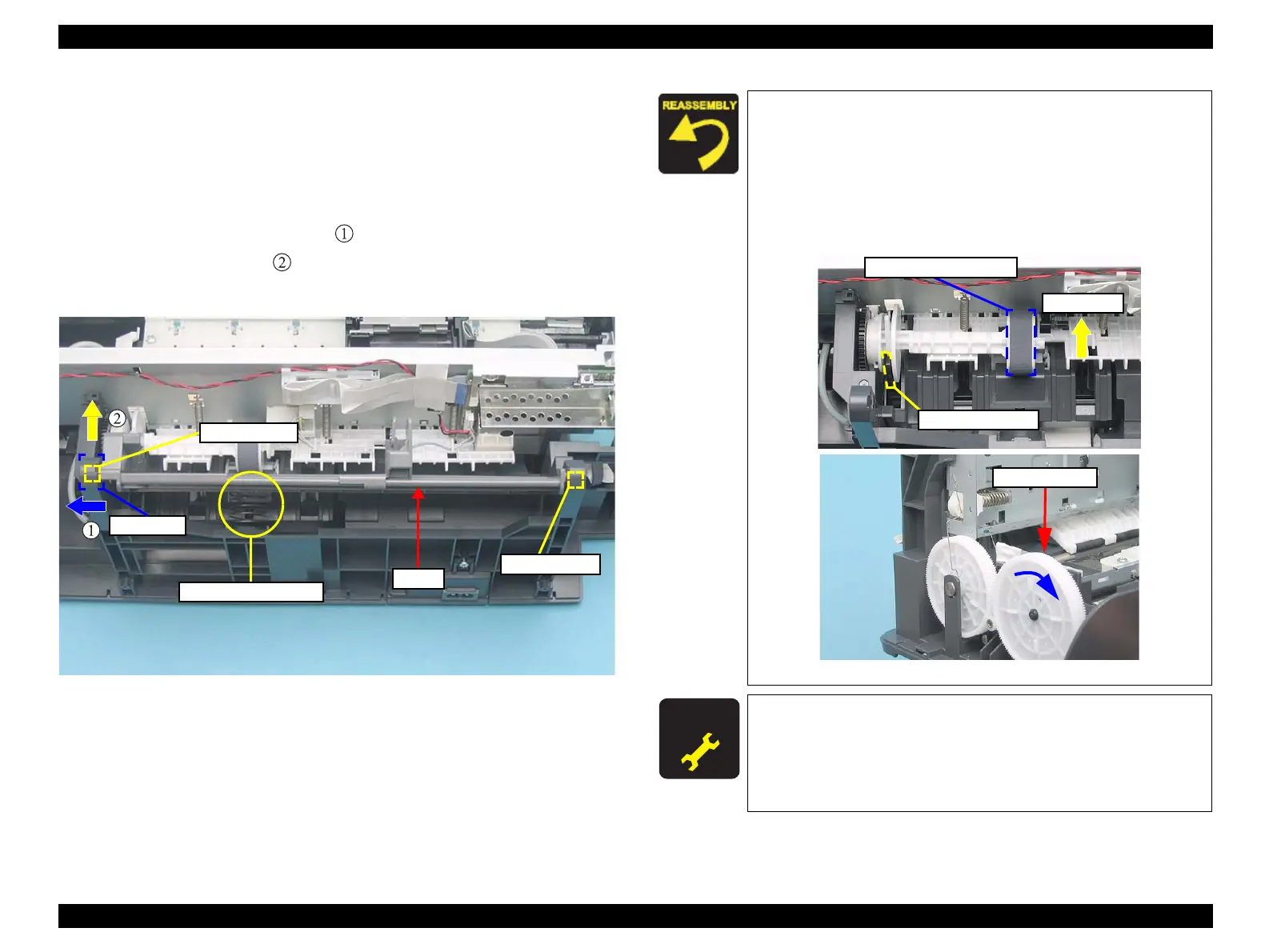
1. Pull open the Bearing slightly (Arrow ), to release the guide pin (A).
2. Remove the Hopper (Arrow ) pulling out the guide pin (B).
3. Remove the Compression Spring 1.94.
Figure 4-39. Removing Hopper and Compression Spring 1.94
Compression Spring 1.94
Hopper
Bearing
Guide Pin (B)
Guide Pin (A)
Before installing the Hopper, be sure to adjust the position of the
LD Roller following the steps below.
1. Unlock the Carriage Lock. (See “4.6.1 Printhead (p75)”)
2. Move the CR Unit to the center of the printer.
3. Adjust the position of LD Roller turning the EJ Roller clockwise.
• LD Roller position: the flat part facing inward.
• Paper Back Lever position: inner most.
Figure 4-40. Installing Hopper and Compression Spring 1.94
A D J U S T M E N T
R E Q U I R E D
After replacing the Hopper, perform the following adjustment
(T.B.D.). (Refer to Chapter 5 “ ADJUSTMENT (p100)”)
1. “TOP Margin Adjustment”
2. “PF Band Adjustment”
EJ Roller
Paper Back Lever
Flat part of LD Roller
Inward

 Loading...


