EPSON Stylus CX4300/CX4400/CX5500/CX5600/DX4400/DX4450 Revision A
DISASSEMBLY/ASSEMBLY Removing Board 73
4.5 Removing Board
4.5.1 Main Board
Part/Unit that should be removed before removing Main Board
Document Cover / ASF Cover / Support Arm / Scanner Unit / Middle Case /
Panel Unit /Printer Mechanism /Hopper
Removal Procedure
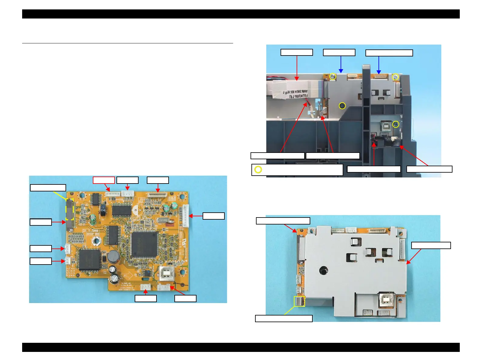
1. Disconnect the following connector cables (x4) and FFCs (x2) from the
connectors on the Main Board Assy.
• CN1: Head FFC
• CN2: Head FFC (Backside)
• J1: Power Supply Board cable
• J7: CR Motor cable
• J8: PF Motor cable
• J9: PE Sensor cable
Figure 4-27. Connector Layout of Main Board
2. Remove the screws (x4), and remove the Main Board Assy.
Figure 4-28. Removing Main Board (1)
3. Remove the Grounding Plate Clip from the Main Board Assy.
4. Remove the Shield Plate from the Main Board.
Figure 4-29. Removing Main Board (2)
J9
J7
CN1
CN2 (backside)
J8J1
J5J6
J3
Not used
PE Sensor Cable
Power Supply Cable
Main Board Assy.
Head FFCs
C.B.S 3X6 (Torque: 8±1Kgf.cm)
CR Motor Cable
Head FFCs
PF Motor Cable
Shield Plate
Grounding Plate Clip
Shield Plate
Main Board Assy.

 Loading...


