EPSON Stylus CX4300/CX4400/CX5500/CX5600/DX4400/DX4450 Revision A
DISASSEMBLY/ASSEMBLY Disassembling Printer Mechanism 85
4.6.7 Power Supply Board
Part/Unit that should be removed before removing LD Roller/ASF Unit
Document Cover / ASF Cover / Support Arm / Scanner Unit / Middle Case /
Panel Unit / Printer Mechanism
Removal procedure
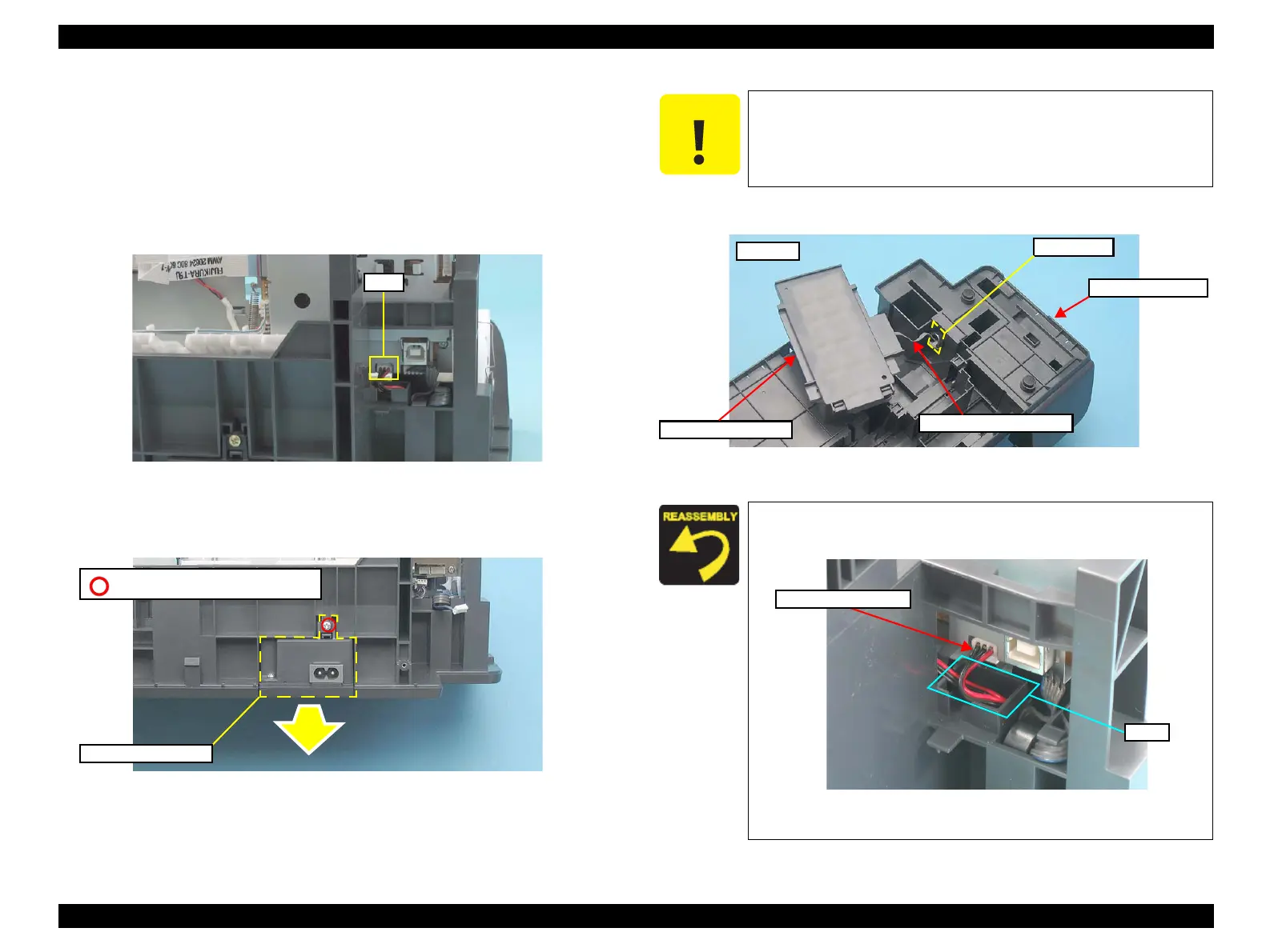
1. Disconnect the connector cable from the connector (J1) of the Main Board.
Figure 4-59. Removing Power Supply Board (1)
2. Remove the screw (x1), and remove the Power Supply Board in the direction
of the arrow.
Figure 4-60. Removing Power Supply Board (2)
3. Pull out the connector cable through the hole of the Frame Base.
Figure 4-61. Removing Power Supply Board (3)
J1
Power Supply Board
C.B.P 3X6 (Torque: 6±1Kgf.cm)
C A U T I O N
Do not turn the Power Supply Board upside down as shown in the
figure below. This figure is only used to show the location of the
parts and the harness arrangement.
When installing the Power Supply Board, arrange the connector
cable into the slot as shown below.
Figure 4-62. Installing Power Supply Board
Power Supply Board
Hole
Connector Cable
Frame Base
Bottom
Slot
Connector Cable

 Loading...


