EPSON Stylus CX4300/CX4400/CX5500/CX5600/DX4400/DX4450 Revision A
DISASSEMBLY/ASSEMBLY Disassembling Printer Mechanism 84
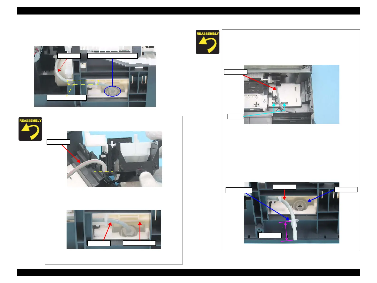
10. Pull out the Ink Tube and the Tube Stopper from the connector of the Waste
Ink Pads, and draw out the tube from the Ink Tube passage.
11. Remove the pump system.
Figure 4-54. Removing Ink System (3)
When installing the Cap Assy, be sure to attach the Ink Tube
up to the edge as shown below without any space between.
Figure 4-55. Installing Ink Tube
When inserting the Ink Tube into the connector, be careful not
to touch the Paper Back Lever.
Figure 4-56. Paper Back Lever behind Ink Tube
>>To be continued to the next page.
Ink Tube Connector of Waste Ink Pad
Ink Tube Passage
Ink Tube
Ink Tube
Paper Back Lever
When installing the Cap Assy, follow the steps described below.
1. Arrange the tube between the ribs as shown in the figure below.
2. Place the Cap Assy and match the tabs (x2) and lock them.
(refer
to Figure 4-51)
3. Attach the Ink Tube.
(refer to Figure 4-52)
Figure 4-57. Installing Ink System
When installing the Pump Assy, follow the steps described below.
1. Match the tabs (x2) of the Pump Assy with the positioning holes
(x2) of the Frame Base.
(refer to Figure 4-53)
2. Pass the Ink Tube through the Ink Tube passage, and insert the
tube into the connector.
(refer to Figure 4-54)
3. Arrange the tube with the Tube Stopper as shown in the figure.
4. Attach the Ink Tube into the hole of the connector of Waste Ink Pad.
Figure 4-58. Installing Ink Tube (2)
Ink Tube
Ribs
Ink Tube
10±1 mm
Connector
Tube Stopper

 Loading...


