EasyManuals Logo

Epson T-B Series Maintenance Manual

Epson T-B Series
160 pages
To Next Page IconTo Next Page
To Previous Page IconTo Previous Page
Page #70 background imageLoading...
Page #70 background image
T3-B T6-B Maintenance 9. Joint #1
58 T-B series Maintenance Manual Rev.1
(9)
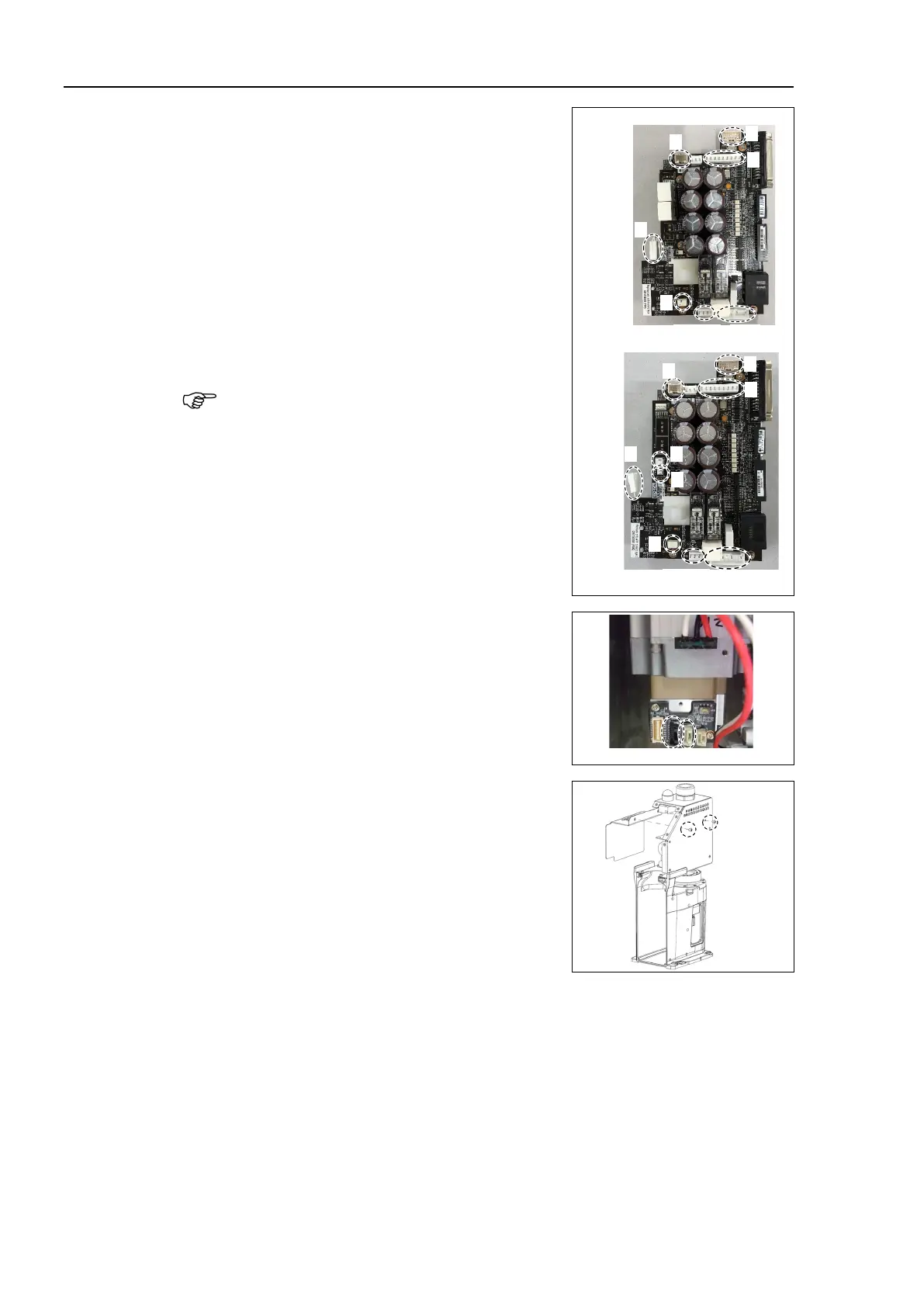
Remove the CPU/DPB board connector.
A: Power connector (IN/OUT ×1 for each)
B: Power cable connector (×1)
C: Signal cable connector
D: Hand I/O connector
E: LED connector
F: Regenerative resistor 1 (T6-B only)
G: Regenerative resistor 2 (T6-B only)
H: Battery connector
Remember the cable layout for reconnecting the
cables correctly after replacement.
E
D
B
C
A-OUT
A-IN
T3-B
H
E
D
B
C
A-OUT
A-IN
F
G
T6-B
H
(10)
Remove the connector of the Joint #1 motor unit.
Signal cable connector (IN/OUT ×1 for each)
OUT
IN
(11)
T3
-B: Remove the power board cover.
NOTE

Table of Contents

Other manuals for Epson T-B Series

Questions and Answers:

Question and Answer IconNeed help?

Do you have a question about the Epson T-B Series and is the answer not in the manual?

Epson T-B Series Specifications

General IconGeneral
BrandEpson
ModelT-B Series
CategoryRobotics
LanguageEnglish

Related product manuals