T3-B T6-B Maintenance 9. Joint #1
T-B series Maintenance Manual Rev.1 59
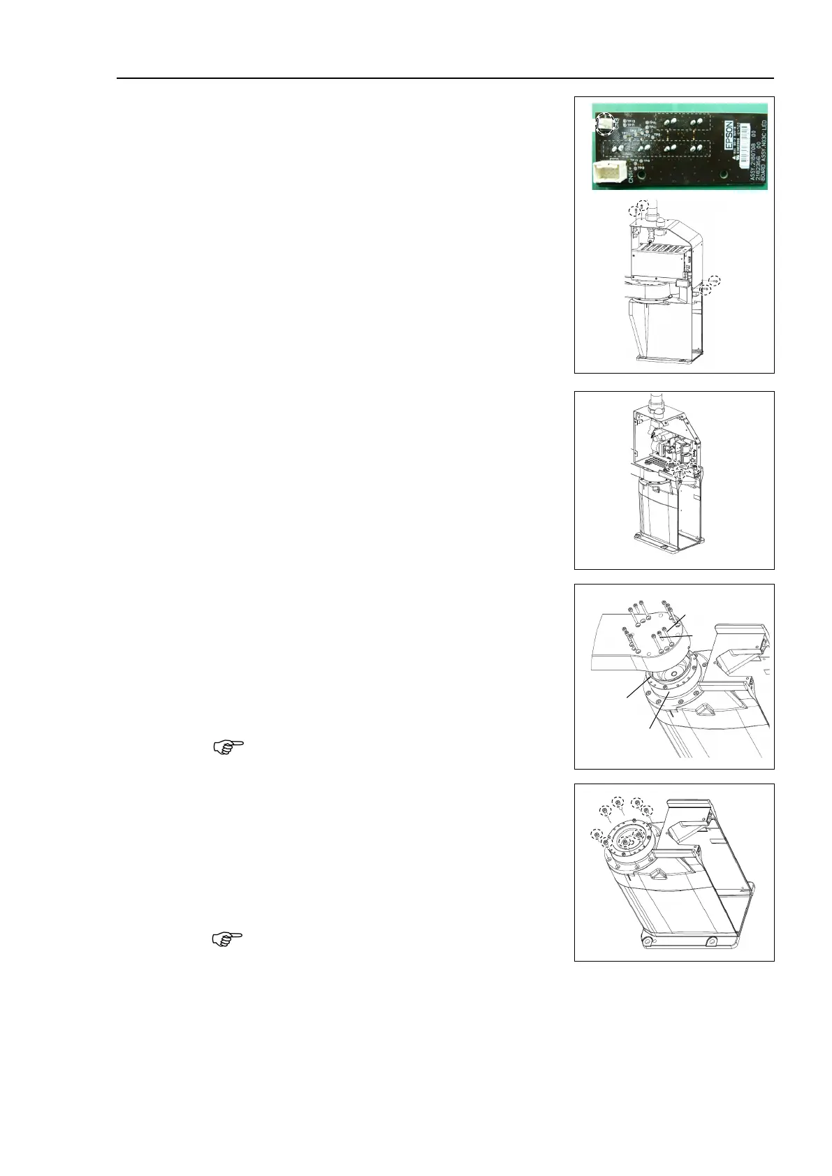
-B: Remove the LED board connector.
A: LED - LED board connector
Cut off the wire tie binding the internal cables.
Then, remove the top board.
Hexagon socket head cap button bolt: 4-M4×10
Unscrew the Power unit mounting screws.
T3-B: 3-M4×10
T6-B: 4-M4×10
Remove power unit from the base.
Remove the Arm #1 mounting bolt in the
Joint #1
T3-B: A: 8-M3×30
B: 4-M3×15
T6-B: A: 8-M4×40
B: 4-M3×20
-ring between the reduction gear units
Be sure not to lose the O-ring.
Remove the screws mounting the Joint #1 flange
on the base.
T3-B: 8-M4×15
T6-B: 6-M5×15
Remove the Joint #1 motor unit from the base.
When removing the Joint #1 motor unit, pull it up
slowly to avoid hitting the base.

 Loading...


