33
Chapter 2 Setup
2
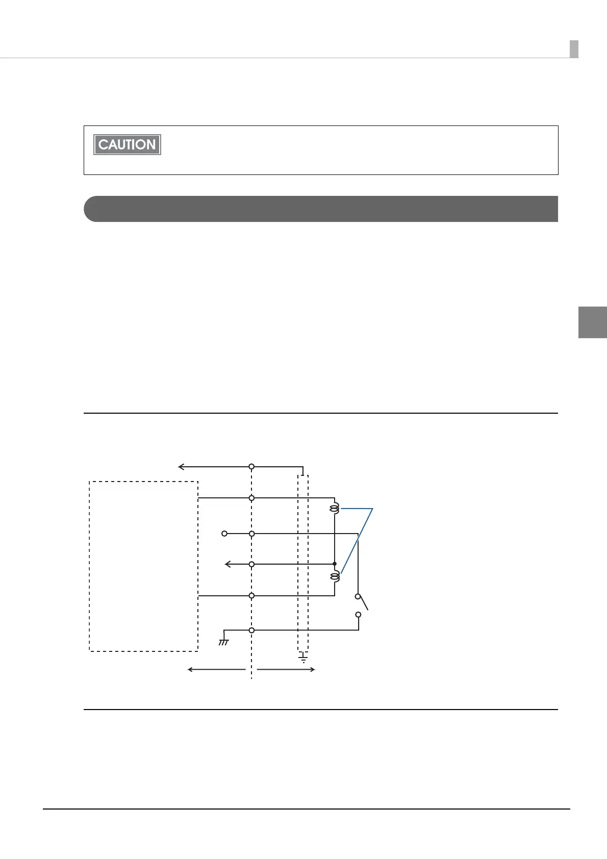
Connecting the Cash Drawer
Cash Drawer Requirements
Specifications of drawers greatly differ depending on manufacturers and models. When you use a drawer
other than specified, make sure its specification meets the following conditions.
Otherwise, devices may be damaged.
• The load, such as a drawer kick solenoid, must be connected between pins 4 and 2 or pins 4 and 5 of the
drawer kick connector.
• When the drawer open/close signal is used, a switch must be provided between drawer kick connector
pins 3 and 6.
• The resistance of the load, such as a drawer kick solenoid, must be 24 ohms or more or the input current
must be 1 A or less.
• Be sure to use the 24 V power output on drawer kick connector pin 4 for driving the equipment.
Drawer Connection Diagram
Connector
Modular connector RJ12
• Two driver transistors cannot be energized simultaneously.
• Leave intervals longer than 4 times the drawer driving pulse when sending it
continuously.
F.G
+24V
With shielded
Drawer kick connector
Printer side User side (Drawer kick side)
Drawer open/
close switch
Drawer kick
solenoid
1
2
3
4
5
6
 Loading...