- 48 -
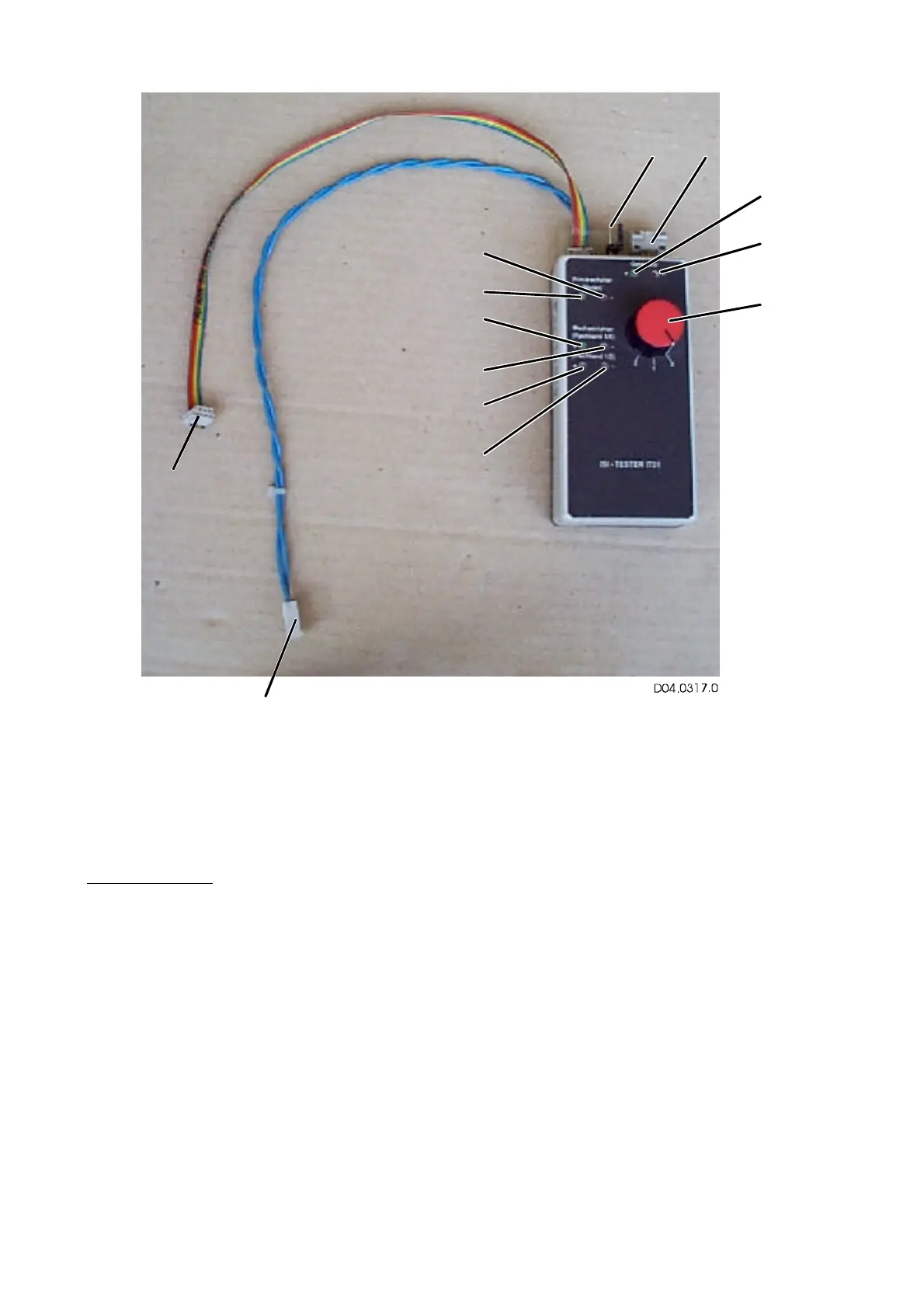
In addition, IT01 comprises three identical check circuits which signal voltages greater than 6 V
by a green LED (d), and voltages smaller than –6 V by a red LED (c). The check circuits check
the control signals from modules A1 and A8 when the MOSFET gates are disconnected.
IT01 can only test the correct function of the drive circuits on the electronic modules A1 and A8
which may suffer damage if there are defects in the power section. The other functions of the con-
trol boards cannot be tested.
Self-test of IT01:
1. Connect 6-way ribbon cable (a) and 2-way Molex (b); this links the signal generator directly
to the check circuits.
2. Selector switch (m).
Switch position 1: Generator LED (k, l), Molex LED (c, d) and ribbon cable LED pins 1, 2
(e, f) blink.
3. Selector switch.
Switch position 2: Generator LED (k, l), Molex LED (c, d) and ribbon cable LED pins 5,6
(g, h) blink.
a
b
c
d
e
f
g
h
i
j
k
l
m