B
A
C D E F G SERVICE
10
B
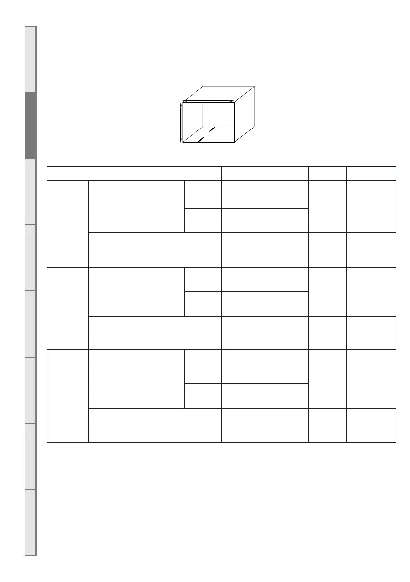
Creating the Cavity
B1 Cavity Shape
The stando rails installed on the outside must only be removed when being installed into a masonry
cavity.
Note: a top is not required when creating the cavity
Height Width Depth
DF700
False Cavity
installation (top standos
must be adjusted to the
upright position)
Framing 600mm
695mm
390mm +
minimum
65mm flue
clearances
Wall
Lining
560mm + allowance
for fascia clearance
*Masonry install with stando rails &
top standos removed.
560mm + allowance
for fascia clearance
685mm 385mm
DF960
False Cavity
installation (top standos
must be adjusted to the
upright position)
Framing 600mm
945mm
405mm +
minimum
65mm flue
clearances
Wall
Lining
560mm + allowance
for fascia clearance
*Masonry install with stando rails &
top standos removed.
560mm + allowance
for fascia clearance
935mm 400mm
DF990
False Cavity
installation (top standos
must be adjusted to the
upright position)
Framing 888mm
945mm
405mm +
minimum
65mm flue
clearances
Wall
Lining
848mm + allowance
for fascia clearance
*Masonry install with stando rails &
top standos removed.
848mm + allowance
for fascia clearance
935mm 400mm
WARNING: Wall lining MUST NOT be installed until after the fireplace is inserted into the cavity. Please
follow the steps in the figures shown.
WARNING: Ensure adequate allowances are made for fascias: see section B9 on page 15.
NOTE: Measure the indicated framing dimensions from the base of the appliance.
NOTE: If cavity dimensions significantly exceed those specified, a register plate is available for purchase
through your local Escea retailer (New Zealand Only).