B
A
C D E F G SERVICE
36
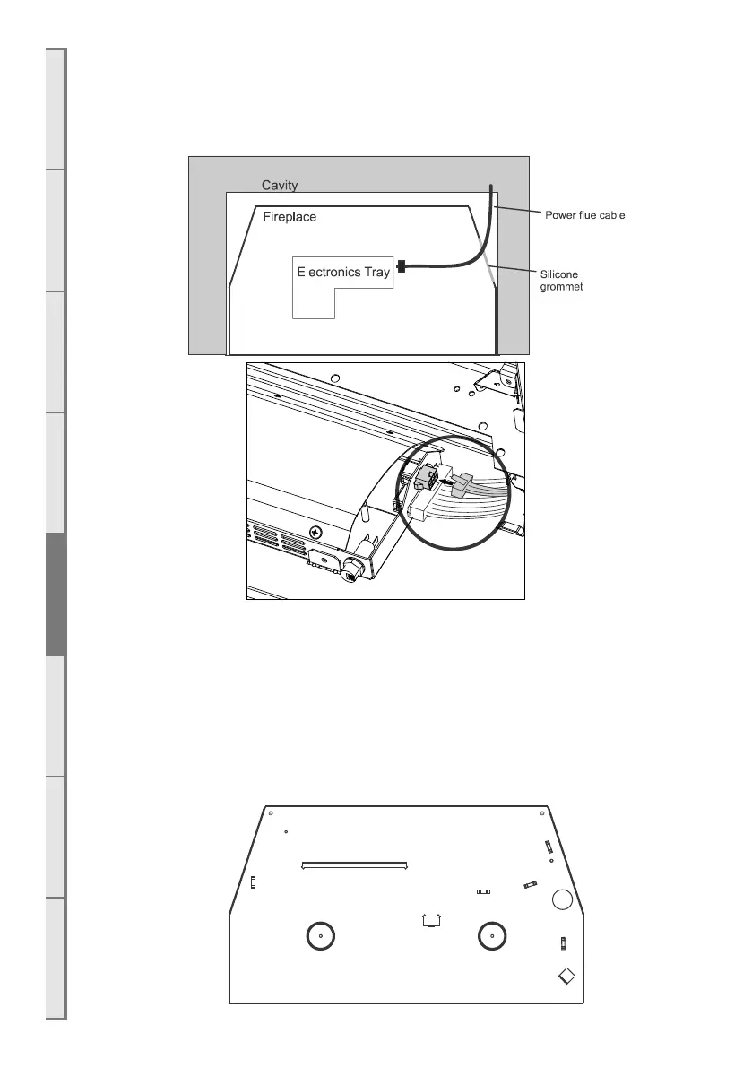
E4 Connecting the Power Flue Cable
NOTE: Make sure to turn o the power supply before connecting the power flue cable. Feed the Power Flue
cable through the silicone grommet on the lower right hand side of the chassis and connect it to the terminal
on the electronics tray shown in the diagram below.
NOTE: the burner tray must be removed to access the electronics tray as shown in section E3 on page
35.
Test the fan now to ensure that it will run prior to continuing with installation. Failure to plug in the fan
will result in an error code when starting the fireplace.
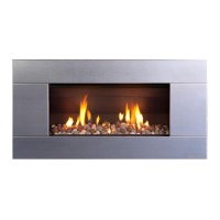
E5 Fixing the Appliance to the Base
An appropriate fastening can be screwed down to the cavity base through the 2 circled holes in the
diagram. For Freestanding installations, 2 machine screws will need to removed from two rivnuts in the
support base of the freestanding and re-applied.
Ensure that the fire is seismically restrained in a manner appropriate to the installation location.