B
ACDEFGSERVICE
55
S5 Removing or Cleaning Fan
As part of regular service procedure, it is recommended that the fan is removed for cleaning. Dust will
build up on the fan rotor and in the cavity where the fan is located. This can be removed by the service
person using a hearth brush and a vacuum cleaner.
ISOLATE THE POWER AND GAS SUPPLY TO THE FIRE BEFORE COMMENCING THIS
PROCEDURE.
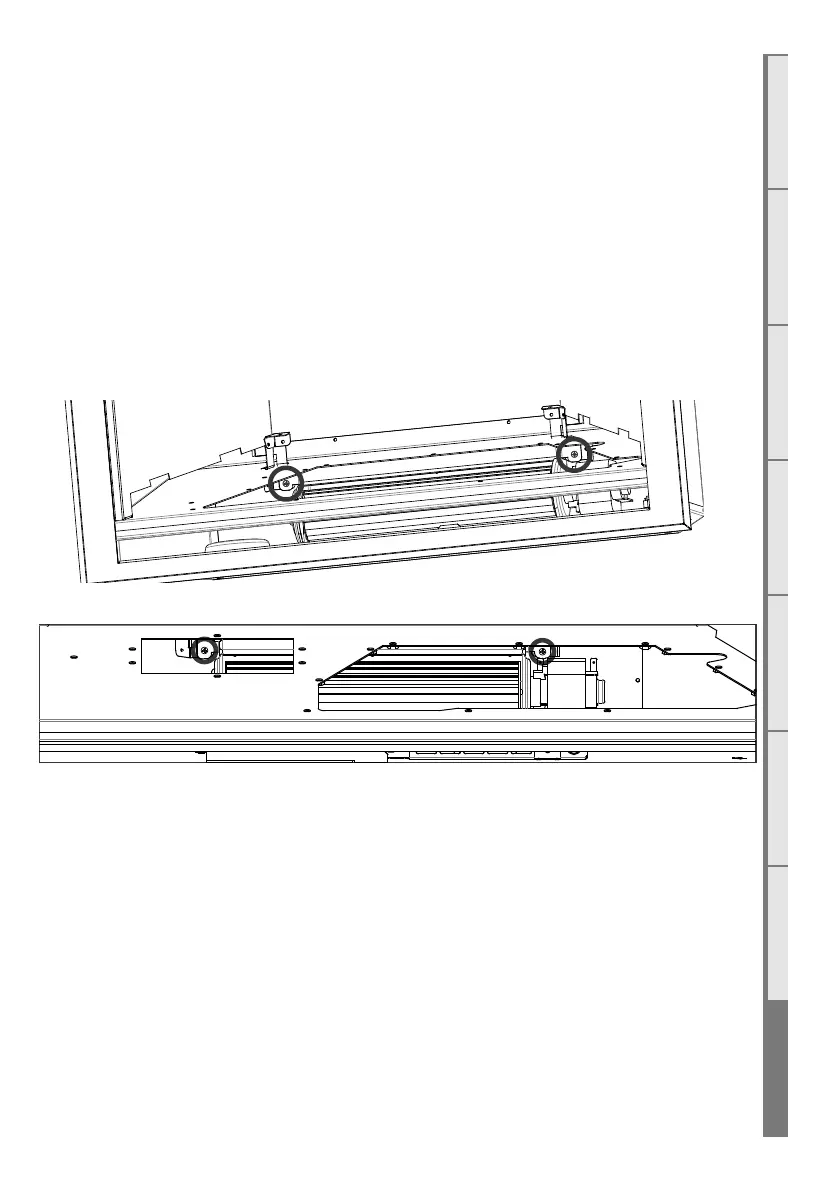
Remove the electronic tray located on the base of the chassis (instructions provided in the next
section) before attempting to remove the room air fan. Disconnect the 3-way fan connector and
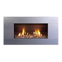
remove the two screws circled in the diagram below (the DF960 and DF990 requires the LH access
hatch to be removed in order to get to the LH screw) . The room air fan can now be pull towards you
and removed through the burner tray hole.
DF700 Fan Screw Locations
DF960 & DF990 Fan Screw Locations
S6 Removing Electronic Tray
ISOLATE THE POWER TO THE FIRE BEFORE THIS PROCEDURE.
All of the electronic components of the heater have been located on a removable tray.
Remove the 18-way connector & 6-way connector from the end of the tray, the network cable, if
installed (both locations circled in diagram shown) and the transformer connector located in the rear
LH corner of the electronics tray.
Remove one self tapping screw in the front face of the electronics tray.
The tray can now be slid towards the RH side then lifted out of the burner tray hole in the firebox.