B
A
C D E F G SERVICE
22
Creating the Hole in the Outside Wall
When cutting the hole in the outside wall, be mindful of how the installation of
the Horizontal Power Flue Wall Terminal will be finished; the installation must
be weatherproof.
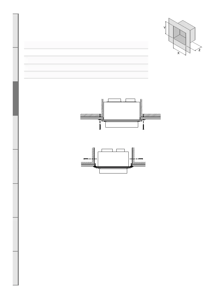
Ideal hole/cavity size for horizontal Power Flue
Without Side Brackets With Side Brackets
X 298mm 360mm
Y 298mm 298mm
Z 175mm
Excluding allowance for flue which exits here
The Horizontal Power Flue Wall Terminal can be attached to the wall in two ways:
A) From the front of the terminal:
B) By attaching the optional wall terminal installation brackets to the sides of the cavity and attaching
the Horizontal Power Flue Wall Terminal to these, from the front:
Attach the Ø100mm and Ø75mm flexible aluminium flues to the spigots on the rear of the Horizontal
Power Flue Wall Terminal using the hose band clamps supplied. Plug the Power Flue electrical cable
into the back of the Horizontal Power Flue Wall Terminal.
For information on the PolyPro flue, see the installation manual which is supplied with the flue
components.
Ensure that the electrical cable is firmly secured to the wall terminal or building to prevent damage or
disconnection if pulled.