B
ACDEFGSERVICE
25
C6 Installing the Universal Vertical Power Flue (Internal Install)
NOTE: For information regarding an external install of the UVP, go to section C7 on
page 26.
The Universal Vertical Power Flue (UVP) internal configuration is designed
to have the fan, mounted within the roof space of the house, and the vertical
Ø225mm diameter liner, containing a Ø100mm flexi, penetrate through the
roof. The UVP internal conversion kit comes with a 1200mm liner that is specific
to the internal installation and must always be used.
Note: The flue setup must comply with either section C1 on page 16 or C2 on
page 18.
Use standard methods to flash the roof penetration. The installation must be
weatherproof and conform to all local council standards including powered flue
termination rules.
Mount the fan mount bracket (1) to the roof framing and strapping using timber
ensuring that the flue is rigid and vertical. Ensure that the mounting timber does
not obstruct access to the 3xM5 screw threads on the side of the fan unit.
Aim to have the fan enclosure (2) mounted as high as possible, mainly to allow
sucient fall for condensation drainage if the flexi-flue is to run horizontally.
Ensure there is sucient space below fan enclosure (2) to have access to fit the
flexi-flue tubes (3) and allow flowing bends if required.
NOTE: The UVP-Internal and the flexi flue connections must be installed in a
location accessible for service or replacement; a service hatch or removable flashing to
allow access is required.
NOTE: When installing the unit onto a flue liner, ensure the length of flue liner above the roof is the
minimum required length. ENSURE the Ø25mm restriction plate is installed on the inlet.
290
229.1
ø226.8
31.6
221.8
250.2
31.6
103.4
TIMBER MUST NOT
OBSTRUCT THESE ZONES
The UVP-Internal kit is intended for use within an accessible roof space or ‘chimney’ construction.
Service access must be provided.
Ensure installation complies with relevant building codes and regulations.
To appliance
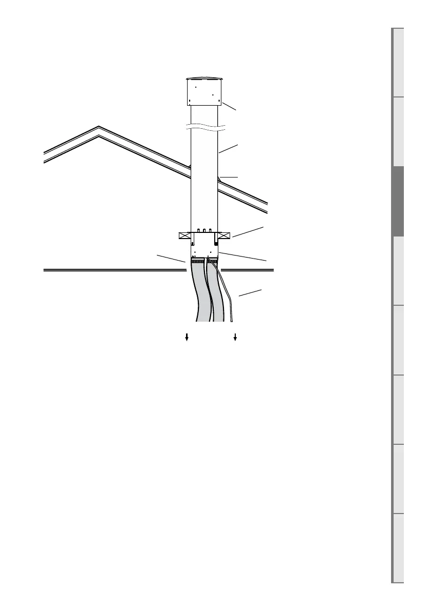
Typical Installation UVP Cowl
‘Decktite’ or similar ashing
1.2m F-F Liner
Hose band clamps
Ø75mmØ100mm
Ensure Power Flue unit
is securely braced using
integral brackets.
Roof Space
Power cord to
appliance
UVP Fan Unit