B
A
C D E F G SERVICE
40
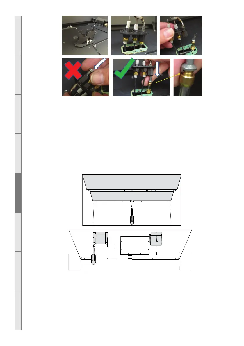
□ Remove the left access hatch (shaded in the second diagram of section E9 on page 37).
Remove the regulator screw cap and screw out the nylon adjuster screw to remove the
existing spring.
□ Replace the current spring with the purple spring supplied in the conversion kit and refit the
nylon adjuster screw.
□ Refit the access hatch using one screw to hold it in place.
□ Refit the burners.
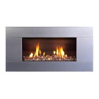
□ For DF990: Remove the firebox bae screw (shown below on the top figure in grey) and
then remove the bae by sliding it upward to release it from the side pins. Remove the
heat exchanger restrictors by unscrewing the 4 fasteners (shown below on the bottom figure
in grey). Rescrew 4 fasteners and then refit the firebox bae.
□ Operate the fire with the glass o and adjust the operating pressure to 2.3kPa for Propane /
ULPG by turning the nylon adjuster screw whilst the appliance is running on maximum.
□ Turn the fire o and remove the burners and access hatch again to replace the metal
regulator cap
□ Adhere the conversion label over the top of the Natural Gas data label on the appliance
data plate.
□ Refit the access panel (all screws), burners, infill and fuel bed.
□ Adhere the ‘Propane’ or ‘ULPG’ label over the top of the existing Natural Gas label on
the side of the appliance (if accessible).