Chapter 4. API Guides
See Why stepping with “next”does not bypass subroutine calls? for potential limitation of using next command.
Checking and setting memory To display or set contents of memory use“Memory”tab at the bottom of“Debug”
perspective.
With the “Memory”tab, we will read from and write to the memory location 0x3FF44004 labeled as
GPIO_OUT_REG used to set and clear individual GPIO’s.
For more information, see ESP32-S2 Technical Reference Manual > IO MUX and GPIO Matrix (GPIO, IO_MUX)
[PDF].
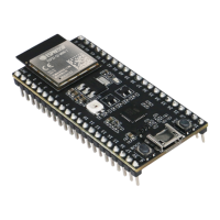
Being in the same blink.c project as before, set two breakpoints right after gpio_set_level instruction. Click
“Memory”tab and then “Add Memory Monitor”button. Enter 0x3FF44004 in provided dialog.
Now resume program by pressing F8 and observe “Monitor”tab.
Fig. 34: Observing memory location 0x3FF44004 changing one bit to “ON”
You should see one bit being flipped over at memory location 0x3FF44004 (and LED changing the state) each time
F8 is pressed.
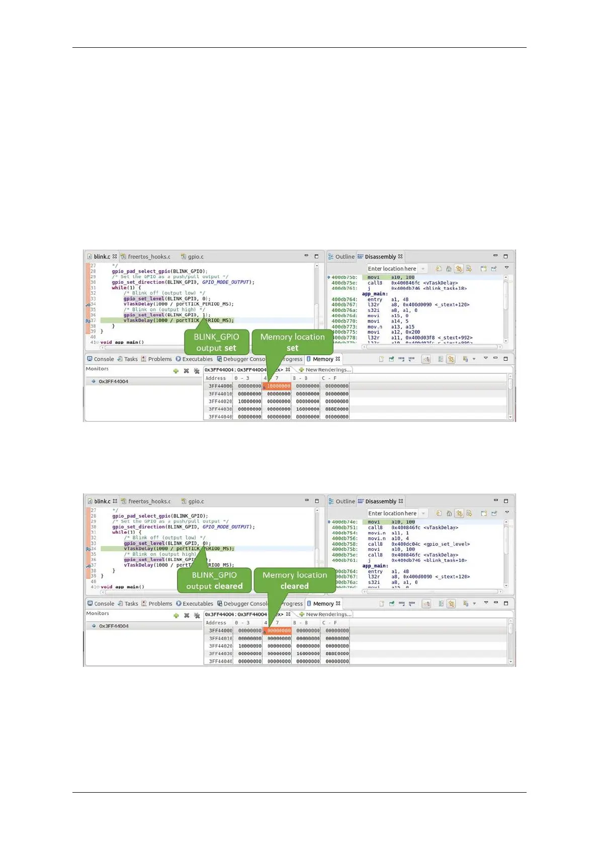
Fig. 35: Observing memory location 0x3FF44004 changing one bit to “OFF”
To set memory use the same“Monitor”tab and the same memory location. Type in alternate bit pattern as previously
observed. Immediately after pressing enter you will see LED changing the state.
Watching and setting program variables A common debugging tasks is checking the value of a program variable
as the program runs. To be able to demonstrate this functionality, update file blink.c by adding a declaration of
Espressif Systems 1401
Submit Document Feedback
Release v4.4